Do you have a question about the Carrier 42NQ012N and is the answer not in the manual?
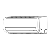
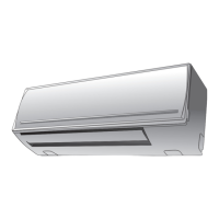
Provides detailed diagrams of the indoor unit's physical structure and dimensions.
Shows diagrams of the outdoor unit's physical structure, dimensions, and air flow.
Lists and specifies electrical parts for the indoor unit.
Lists and specifies electrical parts for the outdoor unit.
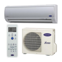
Explains remote control buttons, their functions, and how to operate the unit.
Explains the roles of indoor and outdoor unit controllers and fan control.
Details the operation of Automatic, Fan Only, Cooling, and Dry modes.
Details safety and reliability prevention functions like temp limits and defrost.
Describes Hi POWER mode for faster operation and ECO mode for energy saving.
Explains how to turn off the filter indicator light after cleaning.
Details how to set and cancel the auto restart function for power failures.
Provides crucial safety warnings for installing the air conditioner, especially with R410A.
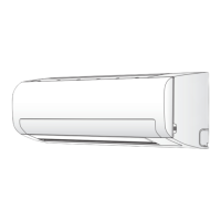
Illustrates the placement and mounting of both indoor and outdoor units.
Lists parts, tools, and fixing methods for installation.
Covers location, wall cutting, electrical, piping, drainage, and fixing for indoor units.
Covers location, piping, evacuation, wiring, and remote control settings for outdoor units.
Covers test operations like gas leak test and auto restart setting.
Guides users through the troubleshooting process, starting with basic checks.
Covers essential checks like power supply and cable connections before fault diagnosis.
Explains how to judge faults via indicators and controller roles.
Guides service mode usage and check codes for diagnosis.
Lists fault codes, symptoms, and recommended actions for diagnosing unit issues.
Flowcharts to diagnose various operational issues like no power or fan failure.
Diagnoses issues with remote control communication and P.C. board.
Instructions for replacing main components of the indoor unit, starting with the front panel.
Procedures for replacing outdoor unit components like cabinets and capacitors.
Exploded view and part number list for indoor unit electronic components.
Exploded view and part number list for indoor unit components.
Exploded view and part number list for outdoor unit components.
| Cooling Capacity | 12000 BTU/h |
|---|---|
| Refrigerant | R410A |
| Net Weight (Indoor Unit) | 9 kg |
| Power Supply | 220-240V, 50Hz |
| Operating Temperature (Cooling) | 18°C |