7. After completing unit conversion, perform all safety checks
and power up unit.
NOTE: The design and installation of the duct system must be in
accordance with the standards of the NFPA for installation of
nonresidence-type air conditioning and ventilating systems, NFPA
90A or residence-type, NFPA 90B; and/or local codes and
residence-type, NFPA 90B; and/or local codes and ordinances.
ADHERE TO THE FOLLOWING CRITERIA WHEN SELECT-
ING, SIZING, AND INSTALLING THE DUCT SYSTEM:
1. Units are shipped for side shot installation.
2. Select and size ductwork, supply-air registers, and return-air
grilles according to American Society of Heating, Refrigera-
tion and Air Conditioning Engineers (ASHRAE) recommen-
dations.
3. Use flexible transition between rigid ductwork and unit to
prevent transmission of vibration. The transition may be
screwed or bolted to duct flanges. Use suitable gaskets to
ensure weather tight and airtight seal.
4. All units must have field-supplied filters or accessory filter
rack installed in the return-air side of the unit. Recommended
sizes for filters are shown in Tables 2 and 3.
5. Size all ductwork for maximum required airflow (either
heating or cooling) for unit being installed. Avoid abrupt duct
size increases or decreases or performance may be affected.
6. Adequately insulate and weatherproof all ductwork located
outdoors. Insulate ducts passing through unconditioned space,
and use vapor barrier in accordance with latest issue of Sheet
Metal and Air Conditioning Contractors National Association
(SMACNA) and Air Conditioning Contractors of America
(ACCA) minimum installation standards for heating and air
conditioning systems. Secure all ducts to building structure.
7. Flash, weatherproof, and vibration-isolate all openings in
building structure in accordance with local codes and good
building practices.
Table 4—Maximum Gas Flow Capacity*
NOMINAL IRON PIPE SIZE (IN.) INTERNAL DIAMETER (IN.)
LENGTH OF PIPE, FT†
10 20 30 40 50 60 70 80 90 100 125 150 175 200
1/2 .622 175 120 97 82 73 66 61 57 53 50 44 40 — —
3/4 .824 360 250 200 170 151 138 125 118 110 103 93 84 77 72
1 1.049 680 465 375 320 285 260 240 220 205 195 175 160 145 135
1 1/4 1.380 1400 950 770 600 580 530 490 460 430 400 360 325 300 280
1 1/2 1.610 2100 1460 1180 990 900 810 750 690 650 620 550 500 460 430
*Capacity of pipe in cu. ft. of gas per hr. for gas pressure of 0.5 psig or less. Pressure drop of 0.5-in. wg (based on a 0.60 specific gravity gas). Refer to Table C-4, National
Fire Protection Association NFPA 54
†This length includes an ordinary number of fittings.
Fig. 13—Supply and Return Duct Opening
C99089
SUPPLY
DUCT
OPENING
RETURN
DUCT
OPENING
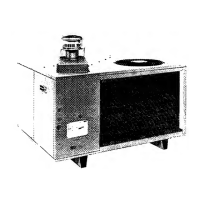
Fig. 14—Vertical Duct Cover Removed
C99012
VERTICAL DUCT COVERS
10

 Loading...