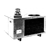
The Carrier 48KHA, KLA series are packaged gas/electric units designed for outdoor installation on rooftops or ground-level slabs. These units combine gas heating and electric cooling in a single, self-contained package. They are design certified in accordance with ANSI Z21.47-1983, ARI Standard 210-81, and ARI Standard 270-84, and are approved by the American Gas Association (AGA) for use with natural or propane gases.
Function Description:
The units provide both heating and cooling for conditioned spaces. They feature an energy-saving automatic, intermittent, electric spark ignition system, eliminating the need for a continuously burning pilot. All units are manufactured with natural gas controls, but can be adapted for propane with appropriate orifices and controls. The heating section operates by igniting gas to warm the air, which is then circulated by the blower motor. The cooling section uses a refrigerant system to remove heat from the indoor air and dissipate it outdoors.
Important Technical Specifications:
- Models: 48KHA, KLA series.
- Gas Type: Natural gas (factory default), convertible to propane.
- Ignition System: Automatic, intermittent, electric spark ignition.
- Refrigerant: Factory charged with R-22.
- Airflow: Designed to handle 350 to 450 cfm per each 12,000 Btuh of rated cooling capacity.
- Heating Input Ratings: Vary by model, ranging from 40,000 Btuh to 150,000 Btuh (see Table 1 for specific model ratings).
- Cooling Capacity: Varies by model, ranging from 17,800 Btuh to 60,000 Btuh (see Table 1 for specific model ratings).
- Electrical Data:
- Voltage/Phase: Available in 208/230-1, 208/230-3, and 460-3 configurations.
- Operating Voltage Range: Specified for each model (e.g., 197-253V for 208/230V units).
- Maximum Circuit Ampacity (MCA): Varies by model, from 8.9A to 43.2A.
- Maximum Fuse Size: Varies by model, from 15A to 60A.
- Minimum Wire Size (AWG): 14 to 8 AWG (75C Copper).
- Maximum Wire Length: Varies by model, from 76 ft to 272 ft.
- Condensate Drain: 3/4-in. MPT drain fitting.
- Dimensions and Clearances: Detailed in Fig. 4, with specific values for different models.
- Weight: Operating and shipping weights vary by model (see Weight Data table).
- Air Filter Area: Required filter areas (standard disposable and cleanable/high capacity) are specified in Table 2, based on ARI-rated cooling or heating airflow at 300 fpm, with pressure drop not exceeding 0.08 in. wg.
- Temperature Rise Range: Approved for heating operation within ranges stamped on the unit rating plate (see Table 5).
- NOx Emissions: Units with '1' in the 4th digit of the model number meet California oxides of nitrogen maximum emission requirements.
Usage Features:
- Outdoor Installation: Designed for robust outdoor use, either on a rooftop or a ground-level concrete pad.
- Duct Connections: Features duct flanges on the supply and return air openings for easy connection to existing or new duct systems. Flexible transitions are recommended to prevent vibration transmission.
- Gas Piping: Requires a separate gas supply line with an accessible, external manual shutoff valve. A sediment trap is recommended in the riser leading to the heating section.
- Electrical Wiring: Requires a separate electrical service with a field-supplied, waterproof, fused disconnect switch. Only copper conductors are to be used. Special procedures are outlined for 208-V operation, including transformer lead changes.
- Thermostat Compatibility: Compatible with suitable room thermostats, with recommendations for manual or automatic changeover types (e.g., HH01AD042, HH07AT174). Heat anticipator setting is crucial for proper heating performance.
- Airflow Adjustment: Blower motor speed connections may need adjustment for 208-V operation to ensure adequate airflow. Heating and cooling airflow can be changed by connecting appropriate color-coded leads to the respective relays.
- Burner Air Shutters: Adjustable to ensure optimum heating performance by controlling primary air to each burner.
- Safety Controls: Equipped with furnace limit switch (opens if leaving-air temperature exceeds 175 F), blower safety switch (activates blower if gas valve fails to close), high-pressure relief valve, and compressor overload protection.
Maintenance Features:
- Periodic Maintenance: Recommended annually by a qualified service person to ensure high performance and minimize equipment failure.
- Air Filter Inspection: Monthly inspection recommended, with cleaning or replacement at least twice during heating and cooling seasons, or when clogged.
- Cooling Coil and Drain Pan: Inspect and clean annually during the cooling season. Ensure proper condensate drainage by maintaining a 3-inch trap and checking for leaks.
- Blower Motor and Wheel: Inspect for cleanliness and lubricate annually. Lubrication frequency depends on continuous (every 2 years) or intermittent (every 5 years) operation. Disassembly procedures are provided for cleaning.
- Heating Section: Inspect and clean before each heating season. This includes checking burner orifices, secondary-air shield, flue baffles, pilot, and heat exchanger for leaks or cracks.
- Gas Control Area: Inspect for gas leaks using a soap-and-water solution.
- Pilot Inspection: Clean soot and carbon from the pilot annually to ensure proper flame sensing and ignition.
- Condenser Coil: Inspect and clean annually. Straighten bent fins with a fin comb. Clean with vacuum cleaner for dirt/lint, or mild detergent and water for oil/grease.
- Condenser Fan: Inspect blades annually for cracks or bends, ensuring proper clearance from the motor. Adjust fan position on the motor shaft if necessary.
- Electrical Controls and Wiring: Inspect and check annually for tightness and proper operation.
- Refrigerant Circuit: Annually inspect tubing connections and unit base for oil accumulations, which indicate a leak. Leak testing and charge adjustment procedures are provided, emphasizing the use of accurate thermometers and pressure gauges.
- Access Panels: Designed for easy removal to facilitate maintenance and inspection.
- Top Removal: Procedures are provided for safe removal of the unit top for comprehensive inspection and cleaning of internal components, including the heat exchanger and coils. Special care is advised to prevent damage to seals and insulation during top removal.