5
Step 1 — Turn off the unit demand for cooling or
heating by using the Scrolling Marquee (see Fig. 12),
located in the unit’s control box. See Fig. 5 for
control box location.
a. Push the ESCAPE key until a blank display
screen is shown.
b. Push the DOWN arrow key until the SERVICE
TEST LED is lit.
c. Push the ENTER key. The display will show
TEST.
d. Push the ENTER key again. The NO/YES dis-
play will flash.
e. Push the UP or DOWN key to toggle the display
to YES and then push ENTER. The unit will be
locked off from heat, cooling or any operation.
The controls will still function and the display
will still operate.
NOTE: A password may be required to change Service
Test values depending on the previous settings configured
in the unit. The default password is “1111.”
Run Status
Service Test
Temperature
Pressures
Setpoints
Inputs
Outputs
Configuration
Time Clock
Operating Modes
Alarms
Alarm Status
ENTER
MODE
ESCAPE
C06320
Fig. 12 -- ComfortLink Controller
Step 2 —
Turn off gas supply by closing the gas supply
shut--off valve (external to RTU unit). See Fig. 13.
C07330
Fig. 13 -- Gas Supply Shut Off Valve
Step 3 —
Turn off the electrical supply to the unit by
switching the RTU main disconnect to off. Then,
ensure personal safety by installing a lockout tag on
the disconnect.
LOCK-OUT
TAG
ON
MAIN
OFF
C07331
Fig. 14 -- RTU Main Disconnect -- Electrical Supply
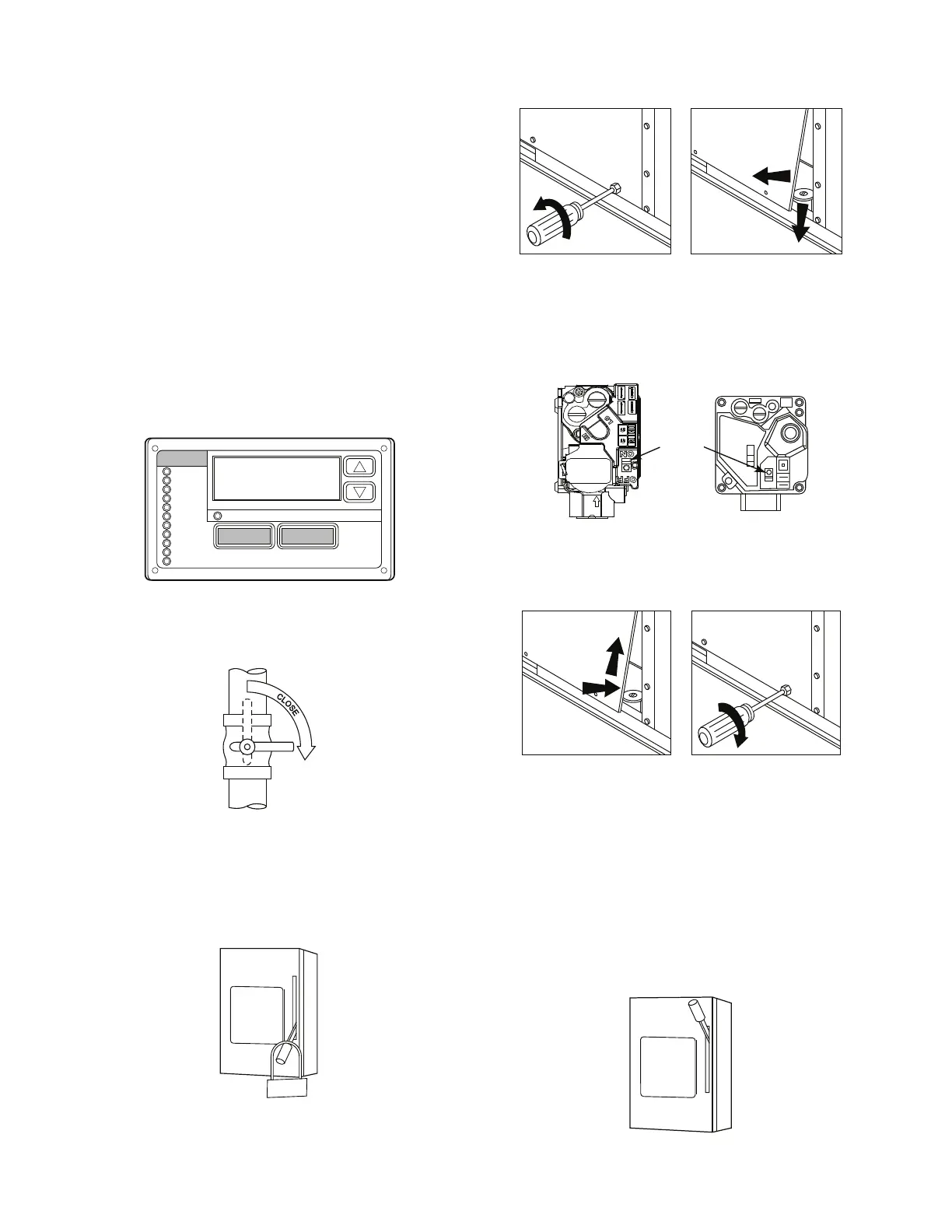
Step 4 —
Remove the gas component access panel.
For location of the gas component access panel, see
Fig. 15.
C08487
Fig. 15 -- Gas Component Access Panel Removal
Step 5 —
Move the RTU gas valve on/off switch to
the OFF position and wait 5 minutes.
Two-Stage
RTU gas valve
300k BTU/Hr
Two-Stage
RTU gas valve
On/Off
Switch
OFF
ON
C11483
Fig. 16 -- Two--Stage Gas Valves
Step 6 —
Replace the gas component access panel.
C08490
Fig. 17 -- Replacing the Gas Component Access Panel
Step 7 —
If the unit is being shut down because of a
malfunction, contact your dealer as soon as possible.
DO NOT proceed to step 8.
Step 8 — If the unit is being shut down because the
heating season has ended, remove the disconnect
lockout tag and restore electrical power to the unit
and take control out of Service Test mode to ensure
operation of the cooling system during the cooling
season.
ON
MAIN
OFF
C07336
Fig. 18 -- RTU Main Disconnect -- Electrical Supply
 Loading...


