6
---.A —
Circuit A
AUX —
Auxiliary Contact
---.B —
Circuit B
---.C —
Circuit C
C—
Compressor, Contactor
CAP —
Capacitor
CB —
Circuit Breaker
CCN —
Carrier Comfort Network
CCH —
Crankcase Heater
COMP —
Compressor
CS —
Current Sensor
EC —
Enthalpy Control
ECB —
Economizer Control Board
FIOP —
Factory-Installed Option
FS —
Flame Sensor
FU —
Fuse
GND —
Ground
GV —
Gas Valve
HPS —
High-Pressure Switch
I—
Ignitor
IAQ —
Indoor-Air Quality
IDM —
Induced-Draft Motor
IFC —
Indoor-Fan Contactor
IFCB —
Indoor-Fan Circuit Breaker
IFM —
Indoor-Fan Motor
IGC —
Integrated Gas Controller
LEN —
Local Equipment Network
LS —
Limit Switch
MBB —
Main Base Board
OAQ —
Outdoor-Air Quality
OAT —
Outdoor-Air Temperature
OFC —
Outdoor-Fan Contactor
OFM —
Outdoor-Fan Motor
PEC —
Power Exhaust Contactor
PEM —
Power Exhaust Motor
PL —
Plug
QC —
Quick Connect
QT —
Quadruple Terminal
RS —
Rollout Switch
SAT —
Supply-Air Temperature
SCT —
Saturated Condensing Temp
SSP —
Saturated Suction Pressure
TB —
Te r mi n a l B l ock
TRAN —
Transformer
T- 5 5 —
Room Temp Device
T- 5 6 —
Room Temp Device with Set
Point Adjustment
Te r mi n a l B l ock
Terminal (Unmarked)
Terminal (Marked)
Splice
Factory Wiring
Field Wiring
To indicate common potential
only, not to represent wiring.
To indicate FIOP or Accessory
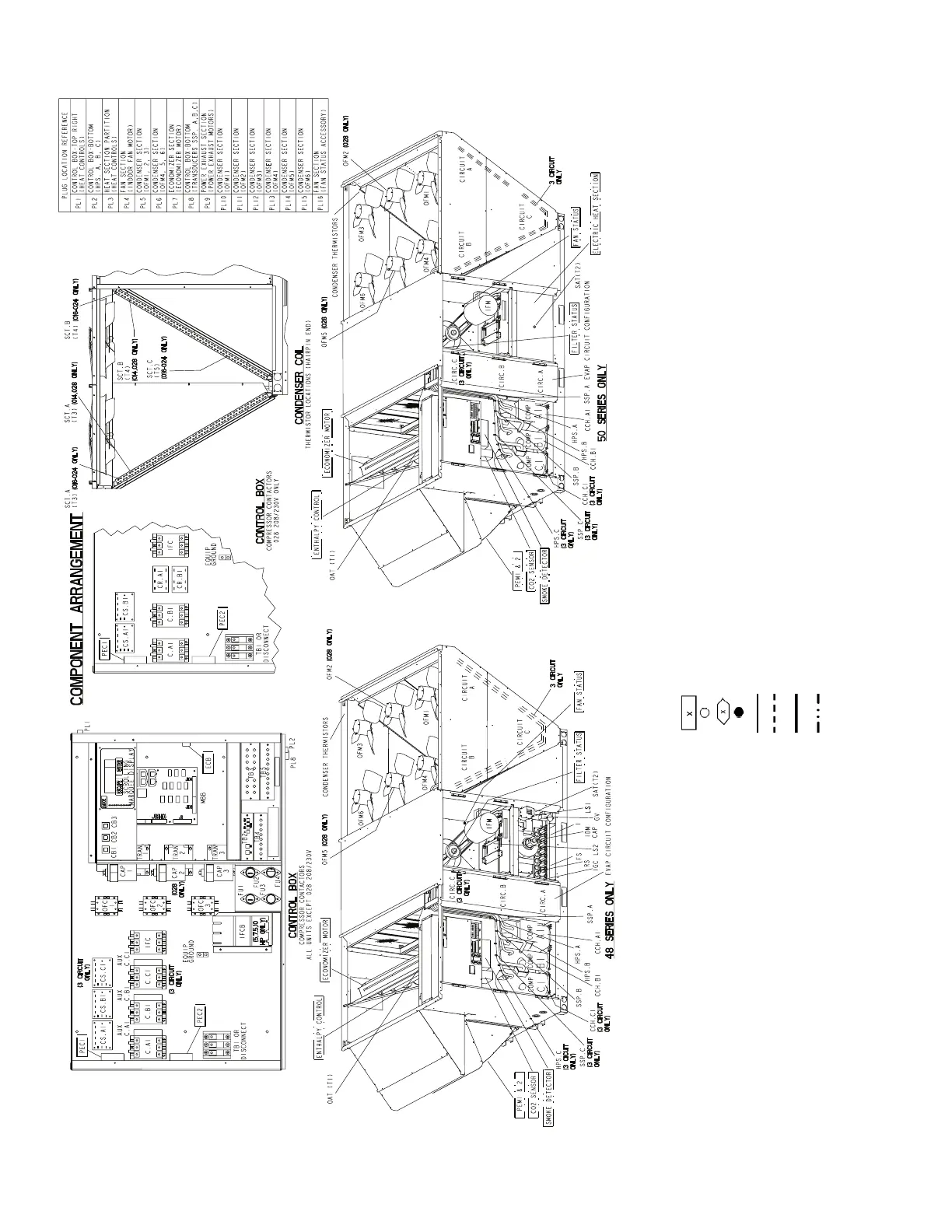
LEGEND FOR FIG. 1 TO 4
THERMOSTAT/IGC MARKINGS
BM —
Blower Motor
C—
Common
CM —
Inducer Motor
CS —
Centrifugal Switch
G—
Fan
IFO —
Indoor Fan On
L1 —
Line 1
R—
Thermostat Power
RT —
Power Supply
SS —
Speed Sensor
W—
Thermostat Heat
W1 —
1st Stage of Heating
W2 —
2nd Stage of Heating
X—
Alarm Output
Y1 —
1st Stage of Cooling
Y2 —
2nd Stage of Cooling
NOTES:
1. Factory wiring is in accordance with the National Electrical
Codes. Any field modifications or additions must be in com-
pliance with all applicable codes.
2. Use 75° C min wire for field power supply. Use copper wires
for all units.
3. All circuit breakers Must Trip Amps are equal to or less than
156% RLA.
4. Compressor and fan motors are thermally protected. Three-
phase motors protected against primary single-phase
conditions.
5. Red jumper wire must be added between R and W1 for
Space Temperature mode and temporarily during Service-
Test mode when the heaters need to operate.
Fig. 4 — Typical Component Arrangement
 Loading...


