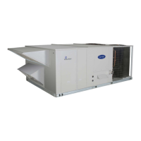
48TC*D08---D14
Nominal 7.5 to 12.5 Tons
Wi t h Pu ro n (R---410A) Refrigerant
Service and Maintenance Instructions
TABLE OF CONTENTS
SAFETY CONSIDERATIONS 1....................
UNIT ARRANGEMENT AND ACCESS 2...........
SUPPLY FAN (BLOWER) SECTION 4..............
COOLING 6....................................
PURONR (R--410A) REFRIGERANT 8..............
COOLING CHARGING CHARTS 10................
CONVENIENCE OUTLETS 16....................
SMOKE DETECTORS 17.........................
PROTECTIVE DEVICES 24.......................
GAS HEATING SYSTEM 25......................
CONDENSER COIL SERVICE 35..................
PREMIERLINKt CONTROL 36...................
RTU--MP CONTROL SYSTEM 44..................
ECONOMI$ER SYSTEMS 57......................
WIRING DIAGRAMS 66.........................
PRE--START--UP 69..............................
START--UP, GENERAL 69........................
START--UP, PREMIERLINK CONTROL 71..........
START--UP, RTU--MP CONTROL 71................
OPERATING SEQUENCES 75.....................
FASTENER TORQUE VALUES 85.................
APPENDIX I. MODEL NUMBER SIGNIFICANCE 87.
APPENDIX II. PHYSICAL DATA 88................
APPENDIX III. FAN PERFORMANCE 90...........
APPENDIX IV. WIRING DIAGRAM LIST 96........
APPENDIX V. MOTORMASTER SENSOR
LOCATIONS 97.................................
UNIT ST ART-UP CHECKLIST 98..................
SAFETY CONSIDERATIONS
Installation and servici ng of air-conditioning equipment
can be hazardous due to system pressure and electrical
compone nts. Only trained and qualifi ed service personnel
should install, repair, or service air-conditioning
equipment. Untrained personnel can perform the basic
maintenance functions of replacing filters. Trained service
personnel should perform all other operati ons.
When working on air-conditioning equipment, observe
precautions in the literature, tags and labels attached to
the unit, and other safety precautions that may apply.
Follow all safety codes. Wear safety glasse s and work
gloves. Use quenching cloth for unbrazing operations.
Have fire extinguishers avail able for all brazing
operations.
Follow all safety codes. Wear safety glasse s and work
gloves. Use quenching cloth for brazi ng operat ions. Have
fire extinguisher available. Read these instructions
thoroughly and follow all warnings or cautions attache d to
the unit. Consult local building codes and National
Electrical Code (NEC) for special requirements.
Recognize safety information. This is the safety--alert
symbol
. When you see this symbol on the unit and in
instructions or manuals, be alert to the potential for
personal injury.
Understand the signal words DANGER, WARNING, and
CAUTION. These words are used with the safety-- alert
symbol. DANGER identifies the most serious hazards
which will result in severe personal i njury or death.
WARNING signifies a hazard which could result in
personal injury or de ath. CAUTION is used to identify
unsafe practices which may result in minor personal
injury or product and property da mage. NOTE is used to
highlight suggestions which will result in enhanced
installation, reliability, or operation.