8
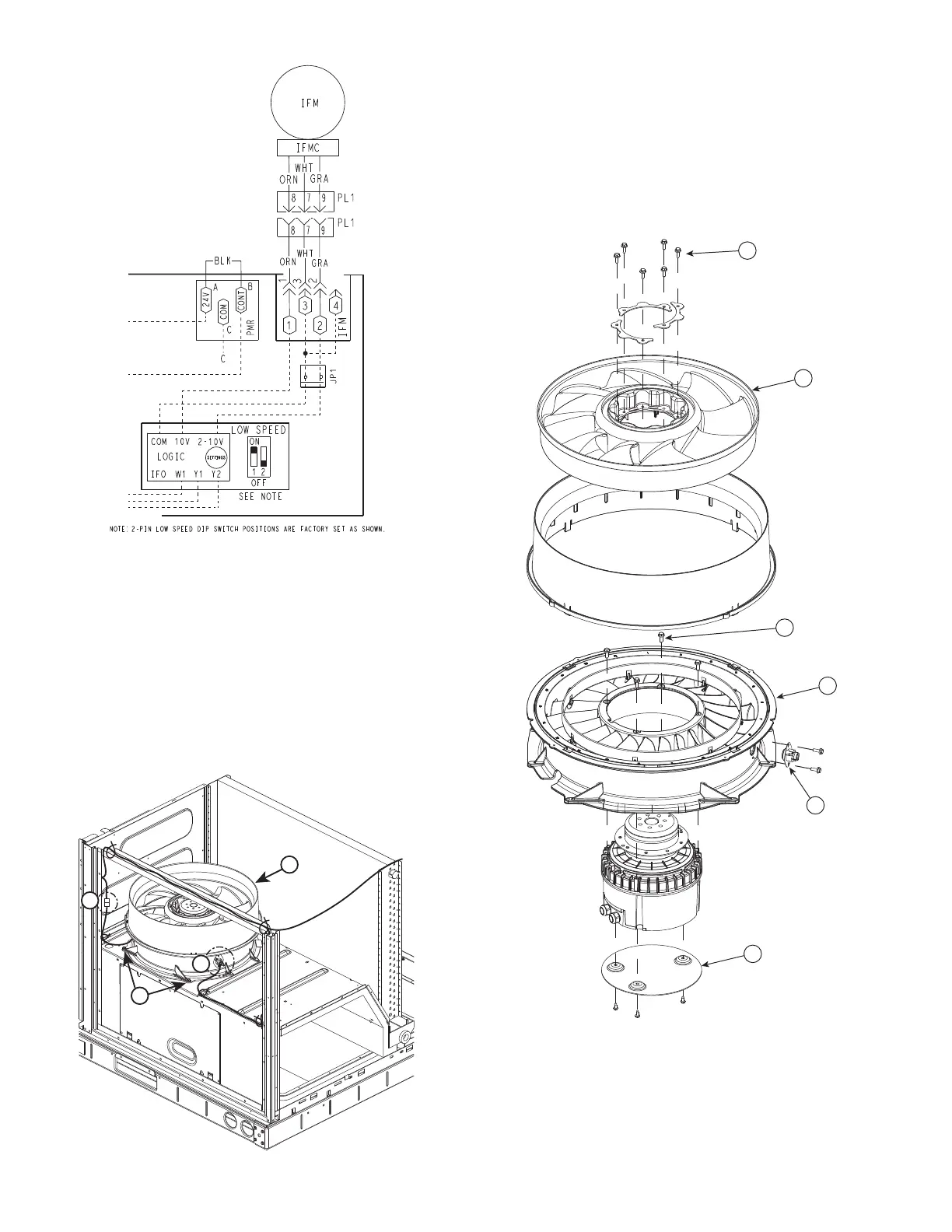
Fig. 10 — Supply Fan Control Wiring Diagram
Removing the Motor and Fan Assembly
NOTE: Due to press fit design of composite Rotor on Motor, it is
highly recommended that any time a motor is replaced the fan
rotor is replaced as well. The rest of the assembly may be reused.
See Fig. 11.
1. Unplug motor harness from control box harness and cut
wire tie at the fan deck.
2. Unplug connectors from stator temperature limit switch.
3. Remove two screws at front of stator on fan deck.
4. Slide fan assembly forward a couple of inches to clear rear
brackets and lift assembly out.
Fig. 11 — Fan Assembly Removal
Disassembling Motor and Fan Assembly
See Fig. 12.
1. Remove six screws from retaining rings in the top of the
fan rotor.
2. Remove rotor from motor.
3. Remove four screws connecting motor to stator flange.
4. Remove stator from motor.
5. If required, remove stator limit switch on aluminum stator.
6. Remove three screws from the heat shield. Retain the heat
shield if a new heat shield has not been ordered.
Fig. 12 — Disassembling Motor and Fan Assembly
Reassembly of Motor and Fan Assembly
See Fig.13.
1. Install heat shield on motor with three #8-32 x
3
/
8
-in.
thread cutting screws (P/N: AK92AB100). Tighten to
30 in.-lb (3.39 Nm).
2. Place motor on flat surface.
1
2
3
4
6
5

 Loading...


