32
RTU OPEN CONTROL SYSTEM
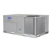
The RTU Open controller is an integrated component of the
Carrier rooftop unit. Its internal application programming
provides optimum performance and energy efficiency. RTU
Open enables the unit to run in 100% stand-alone control
mode, Carrier’s i-Vu
®
Open network, or a Third Party Building
Automation System (BAS). On-board DIP switches allow the
user to select your protocol (and baud rate) of choice among
the 4 most popular protocols in use today: BACnet, Modbus
®1
,
Johnson N2 and LonWorks
®1
. See Fig. 51.
The RTU Open control is factory-mounted in the unit’s main
control box, to the left of the UCB (unit control board). Factory
wiring is completed through harnesses connected to the UCB.
Field connections for RTU Open sensors will be made at the
PCB connectors on the RTU Open board. The factory-installed
RTU Open control includes the supply-air temperature (SAT)
sensor. The outdoor air temperature (OAT) sensor is included
in the FIOP/accessory EconoMi$er
®
2 package.
Sensory/Accessory Installation
There are a variety of sensors and accessories available for the
RTU Open. Some of these can be factory or field installed, while
others are only field installable. The RTU Open controller may
also require connection to a building network system or building
zoning system. All field control wiring that connects to the RTU
Open must be routed through the raceway built into the corner
post of the unit or secured to the unit control box with electrical
conduit. The unit raceway provides the UL required clearance be-
tween high and low-voltage wiring. Pass the control wires through
the hole provided in the corner post, then feed the wires through
the raceway to the RTU Open. Connect the wires to the removable
PCB connectors and then reconnect the connectors to the board.
Fig. 51 — RTU Open Control Module
1. Third-party trademarks and logos are property of their respective
owners.
IMPORTANT: Refer to the specific sensor or accessory
instructions for its proper installation and for rooftop unit
installation refer to base unit installation instructions and the
unit’s wiring diagrams.
WARNING
ELECTRICAL SHOCK HAZARD
Failure to follow this warning could result in personal injury,
death and/or equipment damage.
Disconnect and lockout/tag-out electrical power before wiring
the RTU Open controller.
J4
J2J1
J5 J5
J22
J17
J19
J14
J11
J22
J3
J13
J12
J15
J20
Network Comm
Configurable - Input_8
24 VAC
Configurable - Input_5
24 VAC
Configurable - Input_3
24 VAC
Input_9 (Humidistat)
24 VAC
24 VAC
Input _8 (Enthalpy)
AO-1 (ECON)
Gnd
(OAT)
Gnd
(SAT)
Input_5 (SMK)
Input_4 (R)
BO-5 (Y1)
BO-4 (Y2)
BO-3 (W1)
BO-2 (W2)
BO-1 (G)
Gnd
Input_3 (X)
24 VAC IN
+24 VDC
Input_2 (CO2/RH)
Gnd
+24 VDC
Input_1 (CO2/RH)
Gnd
Board Power
(AO-1)
0-10VDC
4-20mA
BO-6
(H) Humidimizer
BO-8
(Power Exhaust)
LonWorks
Option Card
Port
Example set for
BACnet MS/TP
and 76.8K baud
(1, 2, and 4 ON)
Recommended for all
i-Vu Open installations
Protocol Selector SPT (temp input) BACnet, Modbus, or N2
(LON connection J15)
SPT (common)
SPT (offset input)
*Remove
both for 0-5V
AO-2
GND
(2-10V)
3-Volt
Lithium
Battery
BO-1 BO-2 BO-3 BO-4 BO-5
BO-6
BO-7
BO-8
VAF Output
 Loading...