18
ELECTRICAL DATA
UNIT NOMINAL
VOLTAGE RANGE COMPRESSOR
OFM IFM
ELECTRIC HEAT POWER SUPPLY
NOMINAL
kW
FLA MCA MOCP
MIN MAX RLA LRA FLA FLA
50GL-A24-E-90 4 0 0 --- 3 --- 5 0 380 420 4.5 32.0 0.8 1.1
--- --- 7.5 15
6.5 9.4 13.1 15
8.7 12.6 12.1 20
50GL-A30-E-90 4 0 0 --- 3 --- 5 0 380 420 5.2 35.0 0.8 1.7
--- --- 9.0 15
6.5 9.4 13.9 15
8.7 12.6 17.9 20
13.0 18.8 25.6 30
50GL-A36-E-90 4 0 0 --- 3 --- 5 0 380 420 6.5 46.0 0.8 2.0
--- --- 10.9 15
6.5 9.4 14.3 15
8.7 12.6 18.3 20
13.0 18.8 26.0 30
50GL-A48-E-90 4 0 0 --- 3 --- 5 0 380 420 6.7 50.0 1.3 3.9
--- --- 13.6 20
6.5 9.4 16.6 20
8.7 12.6 20.6 25
13.0 18.8 28.4 30
17.4 25.1 36.3 40
LEGEND
F L A --- Fu l l L o a d A m p s
LRA --- Locked Rotor Amps
MCA --- Minimum Circuit Amps
MOCP --- Maximum Overcurrent Protection
RLA --- Rated Load Amps
NOTES:
1. In compliance with NE C (National Electrical Co de) requirements for mul timotor and combination load equipment (refer to NEC Articles 430 and 440), the
overcurrent protective device for the unit shall be Power Supply fuse. The CGA (Canadian Gas Association) units may be fuse or circuit breaker.
2. Minimum wire size is based on 60 C copper wire. If other than 60 C wire is used, or if length exceeds wire length in table, determine size from NEC.
1. Unbalanced 3 ---Phase Supply Voltage
Never operate a motor where a phase imbalance in supply voltage is greater than 2%. Use the following formula to determine the percentage of voltage
imbalance.
%Voltageimbalance
= 100 x
max voltage deviation from a verage voltage
average voltage
IMPORTANT: If the supply voltage phase imbalance is more
than 2%, contact your local electric utility company immediately .
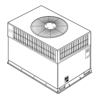
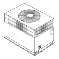
50GL--A

 Loading...