TYP (4) P,LC5 _CORNE8 D
o-&p _1!
0"-8 I/B _
(206)
B
[
5"-7 3/16"
(1707)
OUTDOOR
SECTION
1 3/8" DIA. DRAIN HOLE
6"-11 1/2" (2121)
_1"=7 13115" 1"-4 5/15 _ 1'=4 9115"
I
i
i
i
i
i
i
SUPP[
Am
i
i
i
i
i
i
i
i
i
i
i
i
i
i
i
i
i
i
i
i
i
i
i
i
i
i
(788)
RETURN
AIR
STD UNIT ECONOMIZER
UNIT WEIGHT WEIGHT
Lb I Kg Lb I Kg
50HJ015 1575 714 90 41
50HJ017 1650 748 90 41
7 _CORNER A
_0"=3 15/16" - i " 0"-5 15/15"
(108) 0 (33)5 6 (151)
5"-11 7/E
(1825)
CO.#ERCO%NERCO.oN.CO%NER
•bIKgI,bIKgI,bI*gI,b I*g
4o7165137511701383117414101186
375 170 375 170 449 204 452 205
•50 DIA HOLE ['-12'00
TYPICAL__I 2 31
_; 1 1/4" DIA
7"-2 1/8" [CAL
(2187)
TYPICAL 4 CORNERS
_\_/, L _ _
0._ 03/18- i z0._731 -,2
(_L_L L:- --- _ /I I I_S-. , (157)
//
/ L__ _ .
_.A K._, " _ 1,_ O'- 27 22) (THRU CURB,24V)
(s..NRUCUR_O*SCONN.)/ °0) _ Z#S..... _ o.-3i,8,
COR_ERC 13,_-DIACONCENTRIC_,o._ '_ 50_;is,18_OORRERB(_B)
(35) (THRU CURB POWER)
FILTERS
ACCESS FAR SIDE
.) ?
// - / ///
A_
CO]L
BOX
ACCE55 25_; AIR OR
_I "-10 5118" ECONOMIZER HOOD
(567)
1"-6 3/8" 1
-314" FPT DRAIN CONNECTION
(27) FAR SIDE ONLY
1"-3/18"_"
(310)
(76)
3"-9"
(1143)
(51)
EXHAU5T
(ACCESSORY ONLY)
50HJ017 ONLY
DIM A
ft-in. I mm
3-5 1039
3-2 963
DIM B DIM C
ft-in. Im m I ft-in. Imm
3-5 1054 I1-1o 1559
3-7 1092 1-10 559
NOTES:
1. Refer to print for roof curb accessory dimensions.
2. Dimensions in ( ) are in millimeters.
3. _ Center of Gravity.
E_ Direction of airflow.
4.
5. Ductwork to be attached to accessory roof curb only.
6. Minimum clearance:
• Rear: 7"-0" (2134) for coil removal. This dimension can be reduced to
4'-0" (1219) if conditions permit coil removal from the top.
• Left side: 4"-0" (1219) for proper condenser coil airflow.
• Front: 4'-0" (1219) for control box access.
• Right side: 4"-0" (1219) for proper operation of damper and power
exhaust if so equipped•
• Top: 6'@" (1829) to assure proper condenser fan operation•
• Local codes or jurisdiction may prevail•
7. With the exception of clearance for the condenser coil and the
damper/power exhaust as stated in Note #6, a removable fence or
barricade requires no clearance.
8. Dimensions are from outside of corner post. Allow O'-S/m" (8) on each
side for top cover drip edge.
9. A 90-degree elbow must be installed on the supply ductwork
below the unit discharge for units equipped with electric heaters.
0"-2"(51) 3" g 718 DIA CONCENTRIC K.O.
r-(7B) g (22) (FIELD ROWER)
-- 5"-11 3/8"
(1813) ECONOMIZER OPENING
(?B?)
PER OPEN[NG
/---1
"1
[
'_LJ0:oSL'S:)'°:::F--
VIEWZ=Z
BAROMETRICRELIEF/POWEREXHAUST
(ACCESSORYONLY)
t 0 "qf3"
. _3 5,B',13,8-o. CO.OENTRIO_0 _1;_ (7B)
(92) g (35) (FIELD POWER) * "
0"-4"
7/8 DIA K,O. (CONTROL) _1(31_4" D A HO
(22) LE _ 1(102)
5"-6" _ SECTION A-A
(1576)
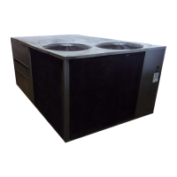
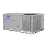
Fig. 4 -- Base Unit Dimensions, 50HJ015, 017

 Loading...


