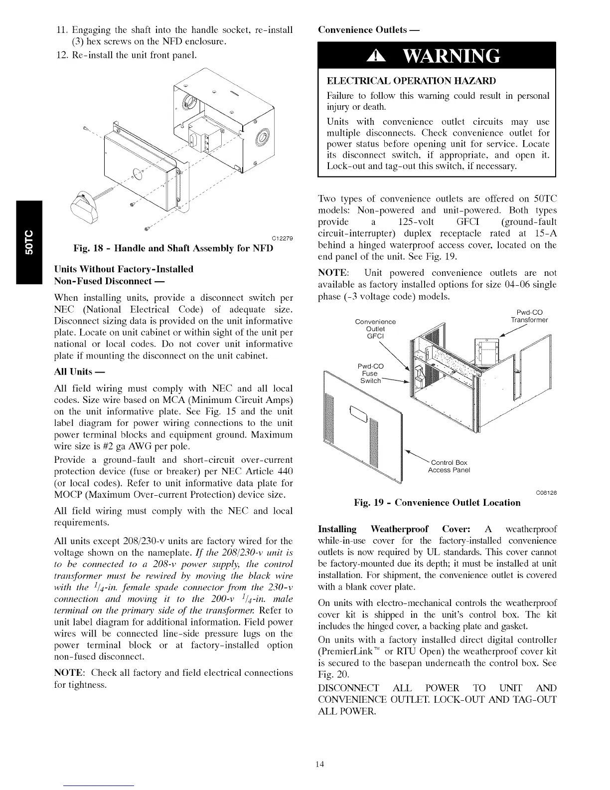
11. Engaging the shaft into the handle socket, re-install
(3) hex screws on the NFD enclosure.
12. Re-install the unit front panel.
Q.
Convenience Outlets-
ELECTRICAL OPERATION HAZARD
Failure to follow this warning could result in personal
injury or death.
Units with convenience outlet circuits may use
multiple disconnects. Check convenience outlet for
power status before opening unit for service. Locate
its disconnect switch, if appropriate, and open it.
Lock-out and tag-out this switch, if necessary.
C12279
Fig. 18 - Handle and Shaft Assembly for NFD
Units Without Factory-Installed
Non-Fused Disconnect --
When installing units, provide a disconnect switch per
NEC (National Electrical Code) of adequate size.
Disconnect sizing data is provided on the unit informative
plate. Locate on unit cabinet or within sight of the unit per
national or local codes. Do not cover unit informative
plate if mounting the disconnect on the unit cabinet.
All Units --
All field wiring must comply with NEC and all local
codes. Size wire based on MCA (Minimum Circuit Amps)
on the unit informative plate. See Fig. 15 and the unit
label diagram for power wiring connections to the unit
power terminal blocks and equipment ground. Maximum
wire size is #2 ga AWG per pole.
Provide a ground-fault and short-circuit over-current
protection device (fuse or breaker) per NEC Article 440
(or local codes). Refer to unit informative data plate for
MOCP (Maximum Over-current Protection) device size.
All field wiring must comply with the NEC and local
requirements.
All units except 208/230-v units are factory wired for the
voltage shown on the nameplate. If the 208/230-v unit is
to be connected to a 208-v power suppl); the control
transformer must be rewired by moving the black wire
with the 1/4-in. female spade connector from the 230-v
connection and moving it to the 200-v 1/4-in. male
terminal on the primary side of the transformen Refer to
unit label diagram for additional information. Field power
wires will be connected line-side pressure lugs on the
power terminal block or at factory-installed option
non-fused disconnect.
NOTE: Check all factory and field electrical connections
for tightness.
Two types of convenience outlets are offered on 50TC
models: Non-powered and unit-powered. Both types
provide a 125-volt GFCI (ground-fault
circuit-interrupter) duplex receptacle rated at 15-A
behind a hinged waterproof access cover, located on the
end panel of the unit. See Fig. 19.
NOTE: Unit powered convenience outlets are not
available as factory installed options for size 04-06 single
phase (-3 voltage code) models.
Convenience
Outlet
Pwd-CO
Transformer
"_"_ Control Box
Access Panel
C08128
Fig. 19 - Convenience Outlet Location
Installing Weatherproof Cover: A weatherproof
while-in-use cover for the factory-installed convenience
outlets is now required by UL standards. This cover cannot
be factory-mounted due its depth; it must be installed at unit
installation. For shipment, the convenience outlet is covered
with a blank cover plate.
On units with electro-mechanical controls the weatherproof
cover kit is shipped in the unit's control box. The kit
includes the hinged cover, a backing plate and gasket.
On units with a factory installed direct digital controller
(PremierLink TMor RTU Open) the weatherproof cover kit
is secured to the basepan underneath the control box. See
Fig. 20.
DISCONNECT ALL POWER TO UNIT AND
CONVENIENCE OUTLET. LOCK-OUT AND TAG-OUT
ALL POWER.
14

 Loading...


