50TC*D
10
A-B
6 (0.25”)
B-C
12 (0.5”)
A-C
12(0.5” )
MAXIMUM ALLOWABLE
DIFFERENCE MM (IN.)
A
B
C
C09386
Fig. 6 -- Unit Leveling Tolerances
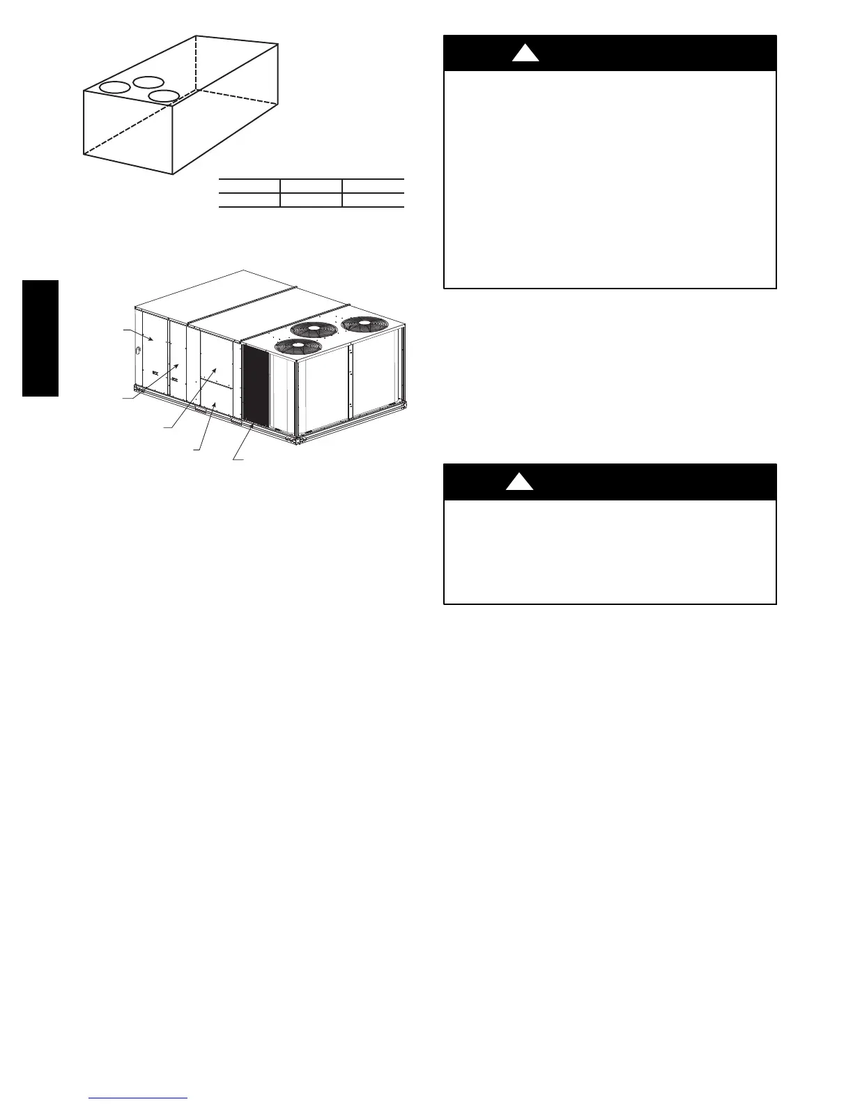
Control Box
ccess Panel
Filter and
Indoor Coil
Access Panel
Indoor Blower
Access Panel
Electric Heat
Access Panel
Compressor
(each side)
C09380
Fig. 7 -- Typical Access Panel and Compressor Locations
Step 5 — Field Fabricate Ductwork
Cabinet return-air static pressure (a negative condition)
shall not exceed 87 Pa (0.5 in. wg) with economizer or
without economizer.
For vertical ducted applications, secure all ducts to roof curb
and building structure. Do not connect ductwork to unit.
Insulate and weatherproof all external ductwork, joints,
and roof openings with counter flashing and mastic in
accordance with applicable codes.
Ducts passing through unconditioned spaces must be
insulated and covered with a vapor barrier.
If a plenum return is used on a vertical unit, the return
should be ducted through the roof deck to comply with
applicable fire codes.
For units with accessory electric heaters:
Minimum clearance is not required around ductwork.
PERSONAL INJURY HAZARD
Failure to follow this warning could cause personal
injury.
For vertical supply and return units, tools or parts
could drop into ductwork and cause an injury. Install
a 90--degree turn in the return ductwork between the
unit and the conditioned space. If a 90--degree elbow
cannot be installed, then a grille of sufficient strength
and density should be installed to prevent objects
from falling into the conditioned space. Due to
electric heater, supply duct will require 90--degree
elbow.
!
WARNING
Step 6 — Rig and Place Unit
Keep unit upright and do not drop. Spreader bars are not
required if top crating is left on unit. Rollers may be used
to move unit across a roof. Level by using unit frame as a
reference. See Table 1 (on page 7) and Fig. 8 for additional
information.
Lifting holes are provided in base rails as shown in Fig. 8.
Refer to rigging instructions on unit.
UNIT DAMAGE HAZARD
Failure to follow this caution may result in
equipment damage.
All panels must be in place when rigging. Unit is not
designed for handling by fork truck.
CAUTION
!
Before setting the unit onto the curb, recheck gasketing on
curb.
PositioningonCurb—
Position unit on roof curb so that the following clearances
are maintained: 6 mm (
1
/
4
in.) clearance between the roof
curb and the base rail inside the right and left, 12 mm
(
1
/
2
in.) clearance between the roof curb and the base rail
inside the front and back. This will result in the distance
between the roof curb and the base rail inside on the
condenser end of the unit being approximately equal to
Detail A in Figs. 4 and 5.
Do not attempt to slide unit on curb after unit is set. Doing
so will result in damage to the roof curb seal.
Although unit is weatherproof, guard against water from
higher level runoff and overhangs.
After unit is in position, remove rigging skids and
shipping materials.
 Loading...


