50TC*D
11
"B"
"C"
"A"
"914-1371"
(36"-54")
DETAIL A
SEE DETAIL A
PLACE ALL SEAL STRIP
IN PLACE BEFORE PLACING
UNIT ON ROOF CURB.
DUCT END
C09107
UNIT
MAX WEIGHT
DIMENSIONS
A B C
KG LB MM IN MM IN MM IN
50TC*D17 923 2035 3249 127.8 1491 58.7 1328 52.3
50TC*D20 930 2050 3249 127.8 1491 58.7 1328 52.3
50TC*D24 998 2200 3595 141.5 1491 58.7 1328 52.3
50TC*D28 1957 2330 3595 141.5 1491 58.7 1532 60.3
NOTES:
1. Dimensions in ( ) are in inches.
2. Hook rigging shackles through holes in base rail, as shown in detail “A.” Holes in base rails are centered around the
unit center of gravity. Use wooden top to prevent rigging straps from damaging unit.
Fig. 8 -- Rigging Details
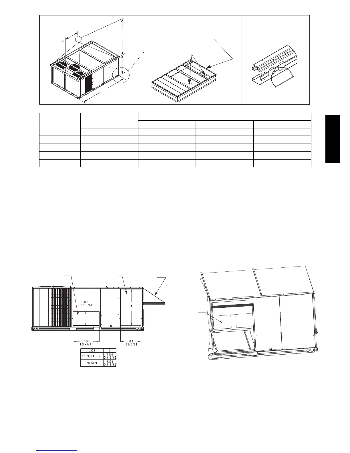
Step 7 — Duct Connection, Horizontal Installation
Field--supplied19mm(
3
/
4
--inch) flanges should be attached
to horizontal duct openings (see Fig. 9) and all ductwork
should be secured to the flanges. Insulate and weatherproof
all external ductwork, joints, and roof or building openings
with counter flashing and mastic in accordance with
applicable codes.
Horizontal Return
Duct Opening
2-Position or Manual
Outside Air
Damper Hood
Horizontal Supply
Duct Opening
NOTE: Dimensions in [ ] are in inches.
C09389
Fig. 9 -- Horizontal Duct Opening Dimensions
Step 8 — Install Outside Air Hood
Economizer and Two Position Hood Removal --
Factory Option
1. The hood is shipped in knock--down form and is loc-
ated in the indoor air compartment. The hood is
strapped to the blower assembly. (See Fig. 10)
Hood
Package
C09150
Fig. 10 -- Hood Package -- Shipping Location
2. To gain access to the hood, remove the back blower
access panel.
3. Locate and cut the strap, being careful to not damage
any wiring.
4. Carefully lift the hood assembly through the back
blower access opening and assemble per the steps
outlined in the following procedure.
 Loading...


