13
COMPRESSOR
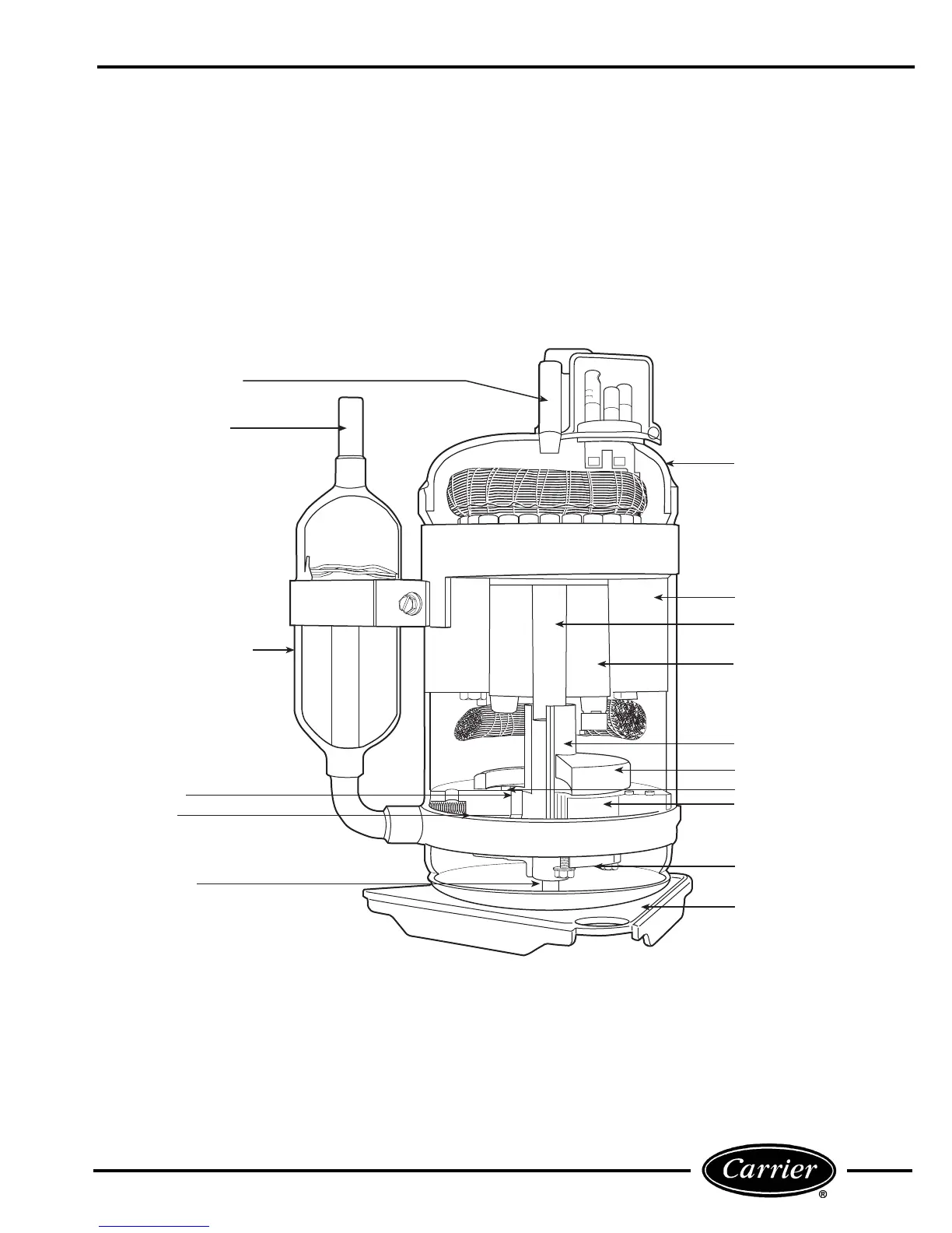
A cutaway view of the rotary compressor with key
components labeled is shown in Figure 27. The motor
stator is rigidly attached to the compressor shell. The
rotor is pressed onto the eccentric shaft, which is sup-
ported by 2 bearings. Both the discharge valve and dis-
charge muffler are attached to the motor bearing. The
pump bearing provides a thrust surface for the shaft
and the rolling piston. Compressed gas is separated
from the suction gas by the vane. Discharge gas pres-
sure and the vane spring keep the vane in contact with
the rolling piston.
DISCHARGE MUFFLER
DISCHARGE VALVE
CYLINDER
PISTON
SUCTION MUFFLER/
ACCUMULATOR
SUCTION INLET
DISCHARGE TUBE
VANE
OIL TUBE
SHELL
STATOR
ECCENTRIC SHAFT
ROTOR
MOTOR BEARING
PUMP BEARING
MOUNTING PLATE
FIGURE 27 — ROTARY COMPRESSOR COMPONENTS
 Loading...