3
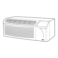
To install the front panel, follow the procedure out-
lined below:
Replace the unit front panel.
1. Hold the front panel firmly at the center top and
center bottom at a 5 to 10 degree angle from
vertical.
2. Place the top of the front panel onto the unit mak-
ing sure the top engagement posts have engaged
the slots on the unit. Front panel should be flat
against the top of the unit.
3. Gently lower the front panel onto the chassis,
ensuring that the power cord (or conduit) is routed
through the front panel notch. Magnetic latches at
bottom of front panel will secure the front panel to
the unit.
To install locking feature on front panel, be sure front
panel is already installed on unit and follow the steps
below:
NOTE: Two field-supplied no. 8,
1
/
2
-in. sheet metal
screws are required to secure front panel to chassis.
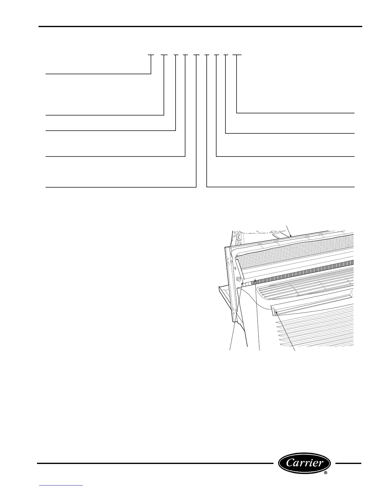
1. Remove both indoor air inlet filters to expose front
panel engagement holes. See Figure 4.
2. Secure front panel to chassis by attaching the
field-supplied screws into engagement holes. Do
not over tighten.
3. Replace both indoor air inlet filters.
NOTE: Front panel alignment may have to be
adjusted slightly to line with chassis.
Electrical Data
3 – 230/208-v, 60 Hz
4 – 265-v, 60 Hz
Cooling Capacity (nominal)
07 – 7,000 Btuh
09 – 9,000 Btuh
12 – 12,000 Btuh
15 – 15,000 Btuh
52 PE A 3 12 3 0 1 AA
Series Designation
PTAC (Packaged Terminal Air Conditioner)
Non-Performance
Changes 0-9
Chassis Options
AA – Standard
CP – Corrosion Protection
RC – Wall Thermostat Control (Not available
on cooling only units)
RP – Wall Thermostat Control with
Corrosion Protection (Not available on
cooling only units)
Packaging
1 – Domestic
Latest Revision
A – Z
Electric Heater Size
2 – 2.3 kW
3 – 3.4 kW
5 – 5.0 kW
Comfort Series
CE – Cooling with Electric Heat
CQ – Heat Pump
PE – Cooling with Electric Heat
PQ – Heat Pump
PC – Cooling Only
Premier Series
FIGURE 3 — MODEL NUMBER NOMENCLATURE
TOP PARTITION
DISCHARGE
DECK
ENGAGEMENT
HOLE
FRONT PANEL
SLOT
FIGURE 4 — FRONT PANEL INSTALLATION
WITH LOCKING FEATURE
 Loading...