2
GENERAL
Thank you for choosing Carrier! You can feel confident
in your selection because the same pride in craftsman-
ship and engineering knowledge that goes into Carrier
equipment at the Astrodome in Texas, the Sistine
Chapel in Rome, the US Capitol Hall of Congress, and
thousands of other installations worldwide has gone
into the construction of this unit.
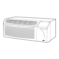
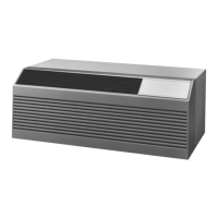
The Carrier package terminal air conditioners and
heat pumps provide a high standard of quality in per-
formance, workmanship, durability and appearance as
they heat and cool the occupied air space year round.
This manual provides information for ease of installa-
tion, operation and maintenance of the 52C and 52P
units. The following units are covered in this manual
(see Figure 1 for additional unit information):
52CE 60 Hz cooling with electric heat units
52CQ 60 Hz cooling, electric heat, and heat pump units
52PE 60 Hz cooling with electric heat units
52PQ 60 Hz cooling, electric heat, and heat pump units
52PC 60 Hz cooling only units
All models are designed for through-the-wall installa-
tion. Separate installation instructions are included
with all accessory components. See Accessories section
on page 15 for complete listing of accessories.
UNIT INSPECTION
Examine unit for damage incurred during shipment.
File a claim immediately with the transit company if
damage is found.
The data information plate (Figure 1) lists the model
number, voltage ranges, and other important electrical
information about this product. Reading and under-
standing this material is important for proper use of
this unit. To access the information plate, the front
panel must be removed; see Figure 2.
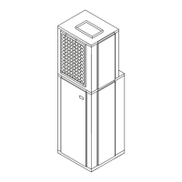
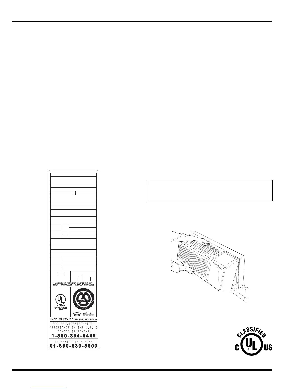
FRONT PANEL
Remove front panel from unit by grasping the panel
firmly at the center top and center bottom. Pull the
panel upward at the bottom and forward at the top to
release magnetic latches and partition hooks. See
Figure 2.
NOTE: Front panel may be secured to chassis with
2 screws located behind indoor air inlet filters. In order
to remove these screws, the filters must be removed
first. Refer to page 11 in this manual for instructions on
removing indoor air inlet filters.
Using Figures 1 and 3 as reference, verify that the
packaged terminal product ordered will operate prop-
erly in your facility. If you do not understand the in-
formation given or have questions about the product,
please call your local dealer or distributor.
Replacement Package Terminal Air Conditioner,
CLASSIFIED BY UNDERWRITERS LABORATO-
RIES INC., AS TO ELECTRIC
SHOCK, FIRE AND CASUALTY
HAZARDS ONLY. FOR FIELD
INSTALLATION WITH EXISTING
WALL SLEEVES, OUTDOOR LOU-
VERS, AND INDOOR PANELS AS
SPECIFIED ON THE PRODUCT.
IMPORTANT: The front panel has to be off the unit
to complete future checks and installation proce-
dures. Do not reinstall front panel at this time.
CANADIAN INSTALLATION
SERIAL 3701X11520
DATE OF MFG. 09/12/2001
VOLT RANGE 187-253
VOLTS 230/208
PH 1
MODEL 52PQA312301AA
HZ
60
MIN CKT AMPACITY 19.3
R-22 OZ 34
DESIGN PSIG 350 HIGH SIDE, 150 LOW SIDE
COOLING
HEATING
BTU/HR 12,100/12,000
AMPS 4.8/5.3
WATTS 1100/1100
EER 11.0/10.9
MOTOR
FAN
COMP
HP
FLA
RLA
LRA
6.1
29
0.75
1/8
BTU/HR 10,800/10,700
AMPS 15.6/14.5
WATTS 3570/2997
COP 3.2/3.2
HEATER
BTU/HR
AMPS 14.8/13.7
WATTS 3400/2850
WATER
STEAM
20
20
20
USE
TIME DELAY FUSE
OR HACR TYPE
CIRCUIT BREAKER
AMP
AMP AMP
MAX FUSE
MAX BREAKER
C
US
FIGURE 1 — SAMPLE DATA INFORMATION PLATE
FIGURE 2 — REMOVING FRONT PANEL
 Loading...