8. The flue pipe must not extend into chimney but be flush with
inside wall.
9. The chimney must extend 3 ft above highest point where it
passes through the roof of a building and at least 2 ft higher
than any portion of a building within a horizontal distance of
10 ft. It shall also be extended at least 5 ft above highest
connected equipment flue collar.
10. Check local codes for any variance.
Factory-Built Chimneys
Listed factory-built chimneys may be used. Refer to chimney
manufacturer’s instructions for proper installation.
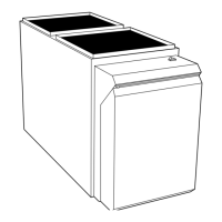
OIL BURNER
This furnace is supplied with a high-pressure atomizing retention
head-type burner (for use with grade 1 or 2 fuel oil). The mounting
flange is fixed to burner air tube and no adjustment is required for
insertion length
OIL CONNECTIONS
Complete instructions for installing fuel oil piping can be found in
oil burner Installation Instructions included with furnace.
Oil line entry holes are provided in side panels. Two holes are
provided in each location so that a 2-pipe system may be used if
desired.
An oil filter should be used with all oil burners and should be
installed as close to burner as possible.
BAROMETRIC DRAFT CONTROL
The barometric draft control shipped with furnace MUST be used
with furnace to ensure proper operation. Instructions for installing
control are packed with control.
ELECTRICAL CONNECTIONS
The unit cabinet must have an uninterrupted or unbroken
electrical ground to minimize personal injury if an electrical
fault should occur. A green ground screw is provided in
control box for this connection.
115-v Wiring
Before proceeding with electrical connections, make certain that
voltage, frequency, and phase correspond to that specified on unit
rating plate. Also, check to be sure that service provided by utility
is sufficient to handle load imposed by this equipment. Refer to
rating plate or Table 7 for equipment electrical specifications.
Make all electrical connections in accordance with National
Electrical Code (NEC) ANSI/NFPA 70-2001 and any local codes
or ordinances that might apply. For Canadian installations, all
electrical connections must be made in accordance with Canadian
Electrical Code CSA C22.1 or subauthorities having jurisdiction.
Do not connect aluminum wire between disconnect switch
and furnace. Use only copper wire. Failure to follow this
caution will lead to intermittent electrical operation and/or
fire hazard.
The control system depends on correct polarity of power supply.
Connect HOT wire (H) and NEUTRAL wire (N) as shown in Fig.
3or4.
A separate line voltage supply MUST be used with a fused
disconnect switch or circuit breaker between main power panel
and unit. (See Fig. 3 or 4.)
Metallic conduit (where required/used) may terminate at side panel
of unit. It is not necessary to extend conduit inside unit from side
panel to control box.
When replacing any original furnace wiring, use only 105°C No.
14 AWG copper wire.
24-V Wiring
Instructions for wiring thermostat (field supplied) are packed in
thermostat box. Make thermostat connections as shown in Fig. 3 or
4 at 24-v terminal board on fan timer board.
Accessories
When installing optional accessories to this appliance, follow
manufacturer’s Installation Instructions included with accessory.
Other than wiring for thermostat, wire with a minimum of type ″T″
insulation (63°F rise) must be used for accessories.
FILTERS
Never operate unit without a filter or with filter access door
removed. Failure to adhere to this warning could lead to a
hazardous condition which could lead to equipment damage
and bodily harm.
An internal filter rack is provided as standard equipment with
furnace and is located in blower compartment. A sufficient
clearance should be provided for air filter access. See Table 8 for
filter rack flange dimensions for return air duct.
START-UP, ADJUSTMENT, AND SAFETY CHECKOUT
Step 1-Operational Checkout
DO NOT TAMPER WITH UNIT OR CONTROLS-CALL
YOUR SERVICE TECHNICIAN. Failure to follow this
warning could result in personal and/or property damage.
Installation of furnace is now complete. Run through the following
checkout and ensure each item has been performed.
Table 7-Electrical Data
UNIT
SIZE
VOLTS-
HERTZ-
PHASE-
OPERATING
VOLTAGE RANGE
MAX
UNIT
AMPS
MIN
WIRE
GAGE
MAX WIRE
LENGTH (FT)
MAX FUSE OR
CKT BKR AMPS
Max Min
105-12 115—60—1 132 104 12.2 14 26 15
120-20 115—60—1 132 104 15.7 12 26 20
Table 8-Filter Size (In.) and Quantity
UNIT
SIZE
AIR FILTER
SIZE
RETURN OPENING
SIZE
SUPPLY OPENING
SIZE
105-12 (2)12X20 20X20 20X20
120-20 (2)16X20 22X20 24X20
6