ELECTRICAL CONNECTION TO J-BOX
Field-Supplied Electrical Box on Furnace J-Box Bracket
See Fig. 24.
1. Remove cover from furnace J-Box.
2. Attach electrical box to furnace J-Box bracket with at least
two field-supplied screws through holes in electrical box into
holes in bracket. Use blunt-nose screws that will not pierce
wire insulation.
3. Route furnace power wires through holes in electrical box and
J-Box bracket, and make field-wire connections in electrical
box. Use best practices (NEC in U.S. and CSA C22.1 in
Canada) for wire bushings, strain relief, etc.
4. Route and secure field ground wire to green ground screw on
J-Box bracket.
5. Connect line voltage leads as shown in Fig. 22.
6. Reinstall cover to J-Box. Do not pinch wires between cover
and bracket.
Electrical Box on Furnace Casing Side
See Fig. 24.
FIRE OR ELECTRICAL SHOCK HAZARD
Failure to follow this warning could result in personal injury,
death, or property damage.
If field-supplied manual disconnect switch is to be mounted
on furnace casing side, select a location where a drill or
fastener cannot damage electrical or gas components.
1. Select and remove a hole knockout in the casing where the
electrical box is to be installed.
→ Table 7—Electrical Data
FURNACE SIZE
VOLTS-
HERTZ-
PHASE
OPERATING
VOLTAGE RANGE
MAXIMUM
UNIT AMPS
UNIT
AMPACITY#
MAXIMUM
WIRE LENGTH (FT)‡
MAXIMUM
FUSE OR CKT BKR
AMPS†
MINIMUM
WIRE GAUGE
Maximum* Minimum*
045-08/024045 115-60-1 127 104 5.3 7.42 49 15 14
045-12/036045 115-60-1 127 104 7.1 9.67 38 15 14
070-08/024070 115-60-1 127 104 5.2 7.22 51 15 14
070-12/036070 115-60-1 127 104 7.3 9.90 37 15 14
070-16/048070 115-60-1 127 104 10.1 13.42 27 15 14
090-14/042090 115-60-1 127 104 8.2 10.84 34 15 14
090-16/048090 115-60-1 127 104 9.9 13.0 28 15 14
090-20/060090 115-60-1 127 104 12.9 16.70 34 20 12
110-12/036110 115-60-1 127 104 8.2 10.76 34 15 14
110-16/048110 115-60-1 127 104 10.1 13.19 28 15 14
110-22/066110 115-60-1 127 104 13.7 17.60 32 20 12
135-16/048135 115-60-1 127 104 10.2 13.28 27 15 14
135-22/066135 115-60-1 127 104 14.5 18.61 30 20 12
155-20/060155 115-60-1 127 104 15.0 19.34 29 20 12
* Permissible limits of the voltage range at which the unit operates satisfactorily.
# Unit ampacity = 125 percent of largest operating component’s full load amps plus 100 percent of all other potential operating components’ (EAC, humidifier, etc.) full
load amps.
† Time-delay type is recommended.
‡ Length shown is as measured 1 way along wire path between unit and service panel for maximum 2 percent voltage drop.
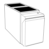
Fig. 23—Relocating J-Box
A02099
TWO
→ Fig. 24—Field-Supplied Electrical Box on
Furnace Casing
A03221
21
→
→
→
 Loading...