4
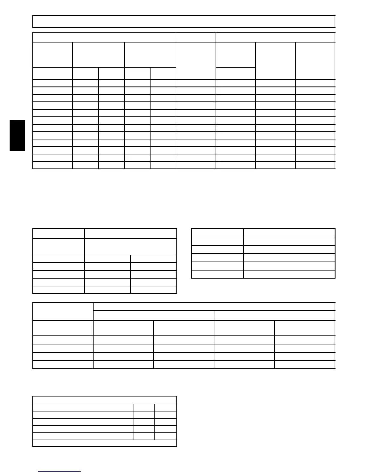
Circulation Air Blower Data -- 58HDV040
Cooling Adjustment Heating Rise Adjustment
DIP Switch
(OFF = 0
ON = 1)
High Cool @ .50
in wc(125 Pa)
Low Cool (80%
of High Cool)
** Adjust
Jumper
Setting
DIP Switch
(OFF = 0
ON = 1)
High Heat
Rise
Change @
0.20 in wc
(50 Pa)
Low Heat
Rise
Change at
Resultant
Static
5&6 CFM L/s CFM L/s 3&4
00 1244 587 995 470 + 00 -- 3 -- 3
*00 1206 569 965 455 *NOM *00 0 0
00 1126 531 901 425 -- 00 4 4
01 1109 523 887 419 + 01 2 2
01 1032 487 826 390 NOM 01 6 6
01 941 444 753 355 -- 01 13 10
10 901 425 721 340 + 10 0 -- 1
10 828 391 662 313 NOM 10 3 3
10 757 357 606 286 -- 10 8 7
11 705 333 564 266 + 11 -- 1 2 -- 1 3
11 633 299 506 239 NOM 11 -- 1 0 -- 1 0
11 556 262 445 210 -- 11 -- 8 -- 8
Airflow performance includes 1” washable filter media.
*Factory Setting
**Adjust Jumper Setting (+, NOM, --) is applied to both Cooling and Heating
Note 1: HP Mode Jumper provides a 10% reduction in airflow when in Comfort position and a call for low or high cooling is
present with the ”O” line off. This feature is to provide lower airflow for running in HP Heating Mode if desirable.
Note 2: DEHUM mode (24VAC on DEHUM terminal) provides a 20% airflow reduction during cooling calls.
Note 3: Low Heat ESP is a result of High Heat ESP (-- is decrease in ris e).
Note 4: High and low heat rise values are approximate air temperature change from return air temperature when at factory
default s ettings.
Table 2 Airflow
DIP Switch
(OFF = 0 / ON = 1)
Continuous Fan @
0.10 in wc (25 Pa) ESP
1&2 CFM L/s
*00 592 279
01 1021 482
10 1346 635
11 1346 635
* Factory Setting
Table 3 SW2 DIP Assignments
DIP Switch Blower Parameter
1&2 Cont Fan Adj
3&4 Heat Speed Adj
5&6 Cool Speed Adj
7&8 Cool On/Off Delay
Table 4
Cooling Delay Options (SW2 -- 7, 8)
ON DELAY OFF DELAY
DIP SW2 -- 7/8
(OFF = 0 / ON = 1)
Timed ON (sec)
Airflow during on
delay
Timer OFF (sec)
Airflow during off
delay
*00 5 OFF 90 100%
01 5 OFF 0 OFF
10 30 50% 30 100%
11 30 50% 180 50%
Airflow % is of High Cool airflow demand determined from SW2--5/6 Table 1
Airflow resumes to 100% after on delay time is completed
Airflow stops (or switches to continuous fan speed) after off delay time is completed
* Factory Setting
MAX CFM’s for Factory Washable Filters
Filter Size (in/mm) CFM L/s
14″ X25″ / 356 x 635 1400 661
16″ X25″ / 406 x 635 1600 755
20″ X25″ / 508 x 635 2000 944
24″ X25″ / 610 x 635 2500 1180
Max CFM based on 600 FPM (3.0 M/s)
NOTE: Disposable filters are typically rated at 300 FPM (1.5 m/s).
These filters only allow half the airflow when compared to 600 FPM (3.0
M/s) filters.
EXAMPLE (approx.):
20in X 25in @ 600 FPM = 2000 CFM, @ 300 FPM = 1000 CFM
508mm x 635mm @ 3.0 M/s = 944 L/s, @ 1.5 M/s = 472 L/s
58HDV
 Loading...


