rating plate. Also, check to be sure that service provided by power
supply is sufficient to handle load imposed by this equipment.
Refer to rating plate or Table 4 for equipment electrical specifi-
cations.
Make all electrical connections in accordance with National
Electrical Code (NEC) ANSI/NFPA 70-2002 and any local codes
or ordinances that might apply. For Canadian installations, all
electrical connections must be made in accordance with Canadian
Electrical Code CSA C22.1 or authorities having jurisdiction.
Use a separate, fused branch electrical circuit containing a properly
sized fuse or circuit breaker for this furnace. See Table 4 for wire
size and fuse specifications. A disconnecting means must be
located within sight from and readily accessible to furnace.
NOTE: Proper polarity must be maintained for 115-v wiring. If
polarity is incorrect, control center fault code indicator light will
flash rapidly and furnace will NOT operate.
Do not connect aluminum wire between disconnect switch
and furnace. Use only copper wire. (See Fig. 28.) Failure to
follow this caution will result in minor unit operation or
performance satisfaction.
The cabinet MUST have an uninterrupted or unbroken ground
according to NEC ANSI/NFPA 70-2002 and Canadian Elec-
trical Code CSA C22.1 or local codes to minimize personal
injury if an electrical fault should occur. This may consist of
electrical wire or conduit approved for electrical ground when
installed in accordance with existing electrical codes. Do not
use gas piping as an electrical ground. Failure to follow this
warning could result in electrical shock, fire, or death.
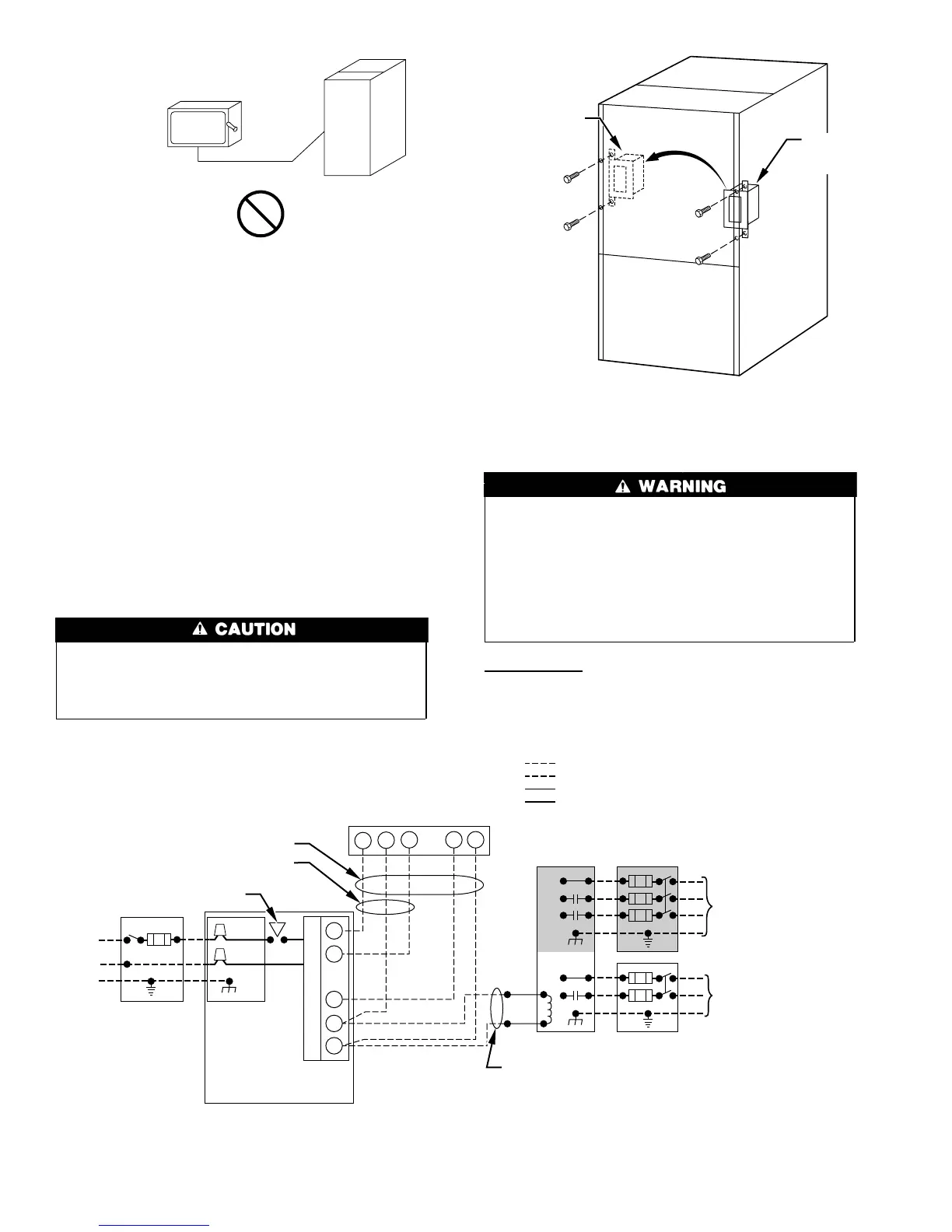
J-Box Relocation
1. Remove 2 screws holding auxiliary J-box. (See Fig. 31.)
2. Rotate J-box 180° and attach box to left side, using holes
provided.
Fig. 29—Disconnect Switch and Furnace
A93033
COPPER
WIRE ONLY
ELECTRIC
DISCONNECT
SWITCH
ALUMINUM
WIRE
Fig. 30—Typical Heating and Cooling Application Wiring Diagram
A02174
115-V FIELD-
SUPPLIED
DISCONNECT
AUXILIARY
J-BOX
24-V
TERMINAL
BLOCK
THREE-WIRE
HEATING-ONLY
FIVE WIRE
NOTE 1
NOTE 2
FIELD-SUPPLIED
DISCONNECT
CONDENSING
UNIT
TWO
WIRE
FURNACE
C
O
N
T
R
O
L
R
G
COM
WCR GY
GND
GND
FIELD 24-V WIRING
FIELD 115-, 208/230-, 460-V WIRING
FACTORY 24-V WIRING
FACTORY 115-V WIRING
208/230- OR
460-V
THREE
PHASE
208/230-V
SINGLE
PHASE
BLOWER DOOR SWITCH
WHT
BLK
WHT
BLK
NOTES: Connect Y-terminal in furnace as shown for proper blower operation.
Some thermostats require a "C" terminal connection as shown.
If any of the original wire, as supplied, must be replaced, use
same type or equivalent wire.
W
Y
GND
THERMOSTAT
TERMINALS
1.
2.
3.
Fig. 31—Relocating J-Box
A00212
FACTORY
INSTALLED
LOCATION
ALTERNATE
FIELD
LOCATION
22
→