Step 4—Multiventing
When 2 or more 58MSA Furnaces are vented near each other, each
furnace must be individually vented. NEVER common vent or
breach vent 58MSA furnaces.
CONDENSATE DRAIN
Step 1—General
Condensate trap is shipped installed in the blower shelf and factory
connected for UPFLOW applications. Condensate trap must be
RELOCATED for use in DOWNFLOW and HORIZONTAL
applications.
Condensate trap MUST be used for all applications.
An external trap is not required when connecting the field drain to
this condensate trap.
The field drain connection (condensate trap or drain tube coupling)
is sized for 1/2-in. CPVC, 1/2-in. PVC, or 5/8-in. ID tube
connection.
Drain pipe and fittings must conform to ANSI standards and
ASTM D1785, D2466 or D2846. CPVC or PVC cement must
conform to ASTM D2564 or F493. Primer must conform to ASTM
F656. In Canada, use CSA or ULC listed schedule 40 CPVC or
PVC drain pipe, fittings, and cement.
When a condensate pump is required, select a pump which is
approved for condensing furnace applications. To avoid conden-
sate spillage, select a pump with an overflow switch.
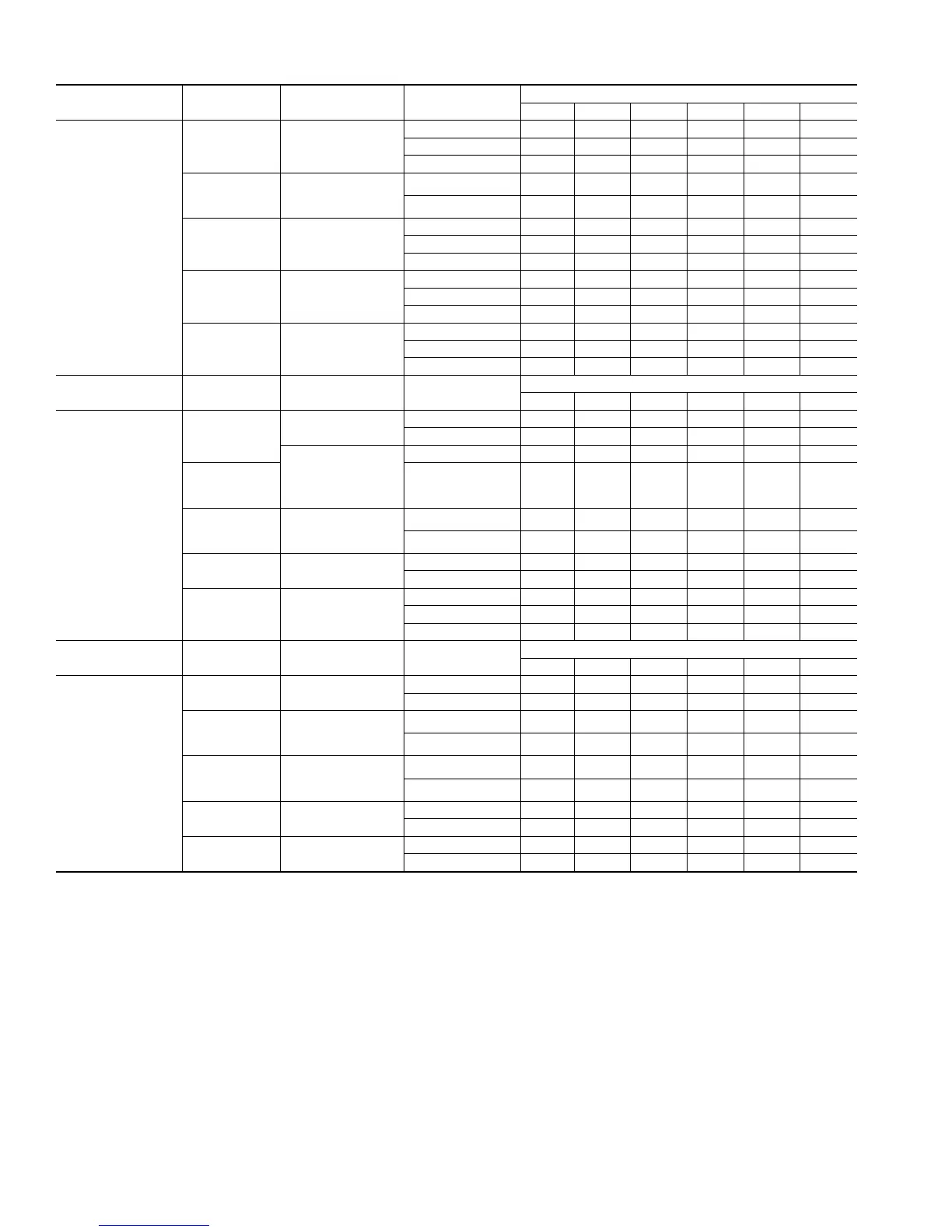
Table 6—Maximum Allowable Pipe Length (ft)
ALTITUDE (FT) UNIT SIZE
TERMINATION
TYPE
PIPE DIA
(IN.)*
NUMBER OF 90° ELBOWS
123456
0 to 2000
040-08
040-12
2 Pipe or 2-in
Concentric
1 5 NA NA NA NA NA
1-1/2 70 70 65 60 60 55
2 707070707070
060-08
060-12
060-16
2 Pipe or 2-in
Concentric
1-1/2 20 15 10 5 NA NA
2 707070707070
080-12
080-16
080-20
2 Pipe or 2-in
Concentric
1-1/2 10 NA NA NA NA NA
2 555035303020
2-1/2 70 70 70 70 70 70
100-16
100-20
2 Pipe or 3-in
Concentric
2 5 NA NA NA NA NA
2-1/2 40 30 20 20 10 NA
3 707070707070
120-20
2 Pipe or 3-in.
Concentric
2-1/2 one disk 10 NA NA NA NA NA
3† 45 40 35 30 25 20
3† no disk 70 70 70 70 70 70
ALTITUDE (FT) UNIT SIZE
TERMINATION
TYPE
PIPE DIA
(IN.)*
NUMBER OF 90° ELBOWS
123456
2001 to 3000
040-08
040-12
2 Pipe or 2-in
Concentric
1-1/2 67 62 57 52 52 47
2 707070707070
2 Pipe or 2-in
Concentric
1–1/2 17 12 7 NA NA NA
060-08
060-12
060-16
2 706766616161
080-12
080-16
080-20
2 Pipe or 2-in
Concentric
2 494430252515
2-1/2 70 70 70 70 70 70
100-16
100-20
2 Pipe or 3-in
Concentric
2–1/2 35 26 16 16 6 NA
3 707070706661
120-20
2 Pipe or 3-in.
Concentric
3 14 9 NA NA NA NA
3† no disk 70 70 63 56 50 43
4† no disk 70 70 70 70 70 70
ALTITUDE (FT) UNIT SIZE
TERMINATION
TYPE
PIPE DIA
(IN.)*
NUMBER OF 90° ELBOWS
123456
3001 to 4000
040-08
040-12
2 Pipe or 2-in
Concentric
1-1/2 64 59 54 49 48 43
2 707070707070
060-08
060-12
060-16
2 Pipe or 2-in
Concentric
1–1/2 16 11 6 NA NA NA
2 686362575756
080-12
080-16
080-20
2 Pipe or 2-in
Concentric
2 464128232213
2-1/2 70 70 70 70 70 70
100-16
100-20
2 Pipe or 3-in
Concentric
2-1/2 33 24 15 14 5 NA
3 707070666156
120-20
2 Pipe or 3-in.
Concentric
3† no disk 65 58 51 44 38 31
4† no disk 70 70 70 70 70 70
See notes at end of table
30