d. Permanently attach elbow/perforated disk assembly to
straight portion of pipe using RTV or by cementing. (See
Fig. 35.)
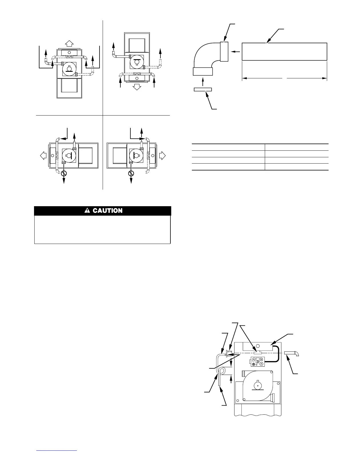
2. Attach combustion-air inlet pipe.
a. Determine location of combustion-air intake pipe connec-
tion to combustion-air intake housing as shown in Fig. 34
for application.
b. Reposition combustion-air intake housing plug fitting in
appropriate unused intake housing connection.
c. Install pipe support (factory-supplied in loose parts bag)
into selected furnace casing combustion-air pipe hole. Pipe
support should be positioned at bottom of casing hole.
d. Insert assembled combustion-air inlet pipe into intake
housing.
e. Make sure elbow is oriented in an acceptable direction and
that the minimum clearance of 3 in. is observed. (See Fig.
34.)
f. Drill a 1/8-in. hole in 2-in. combustion-air inlet pipe using
hole in intake housing as a guide.
g. Install a field-supplied No. 6 or No. 8 sheet metal screw
into combustion-air pipe.
h. Install casing hole filler cap (factory-supplied) in loose
parts bag) in unused combustion-air pipe casing hole.
NOTE: Do not attach combustion-air intake pipe permanently to
combustion-air intake housing since it may be necessary to remove
pipe for service of ignitor or flame sensor.
COMBUSTION-AIR INTAKE HOUSING PLUG
FITTING
The combustion-air intake plug fitting must be installed in
unused combustion-air intake housing. This fitting must be
attached by using RTV sealant, or by drilling a 1/8-in. hole in
fitting, using hole in intake housing as a guide. Install a
field-supplied No. 6 or No. 8 sheet metal screw.
NOTE: DO NOT OVERTIGHTEN SCREW. Breakage of intake
housing or fitting may cause air leakage to occur.
A plugged drain connection has been provided on this fitting
for use when moisture is found in combustion-air intake pipe
and combustion box. If use of this drain connection is desired,
drill out fitting’s tap plug with a 3/16-in. drill and connect a
field-supplied 3/8-in. tube. This tube should be routed to open
condensate drain for furnace and A/C (if used), and should be
trapped. (See Fig. 36.)
Fig. 34—Combustion-Air and Vent Pipe
Connections
Make sure there is adequate clearance (3-in. minimum) to any
fixed or loose objects in order to ensure an adequate
combustion-air supply. Failure to follow this caution will
result in minor unit operation or performance satisfaction.
A96188
COMBUSTION-
AIR
COMBUSTION-
AIR
AIR
FLOW
VENT
VENT
VENT
AIR
FLOW
AIR
FLOW
AIR
FLOW
UPFLOW DOWNFLOW
HORIZONTAL-LEFT DISCHARGE HORIZONTAL-RIGHT DISCHARGE
Select 1 vent pipe connection and
1 combustion-air pipe connection.
COMBUSTION-
AIR
COMBUSTION-
AIR
COMBUSTION-
AIR
COMBUSTION-
AIR
NOTE: Select 1 vent pipe connection and
1 combustion-air pipe connection.
NOTE:
VENT
VENT
VENT
Fig. 35—Combustion-Air Inlet Pipe Assembly
Length of Straight Pipe Portion of
Combustion-Air Inlet Pipe Assembly (In.)
CASING WIDTH A
17-1/2 8-1/2 ± 1/2
21 10-1/2 ± 1/2
24-1/2 12 ± 1/2
A96211
FIELD-SUPPLIED
2-IN. DIAMETER
PVC PIPE
FIELD-SUPPLIED
2-IN. DIAMETER
PVC 90° ELBOW
COMBUSTION-AIR DISC
(FACTORY-SUPPLIED IN
LOOSE PARTS BAG)
A
Fig. 36—Air Intake Housing Plug Fitting Drain
A96190
COMBUSTION–
AIR PIPE
BURNER
BOX
COMBUSTION–AIR
INTAKE HOUSING
3/8
″ ID TUBE
TRAP
TO OPEN
DRAIN
3/16
″
DRILL
HOUSING
PLUG
4″
MIN
27