3. Outdoor openings shall be sized as %llows:
a. (alculate the Ratio of all Indoor Space volume divided by
required volume fbr Indoor (ombustion Air Method
below.
b. Outdoor opening size rednction Factor is 1 minus the
Ratio in a. above.
c. Minimum size of Outdoor openings shall be the size
required in Outdoor Combus{ion Air Method above
multiplied by reduction Factor in b. above. The mininlnnl
dimension of air openings shall be not tess than 3 in. (80
111111) 0
BNSTALLATION
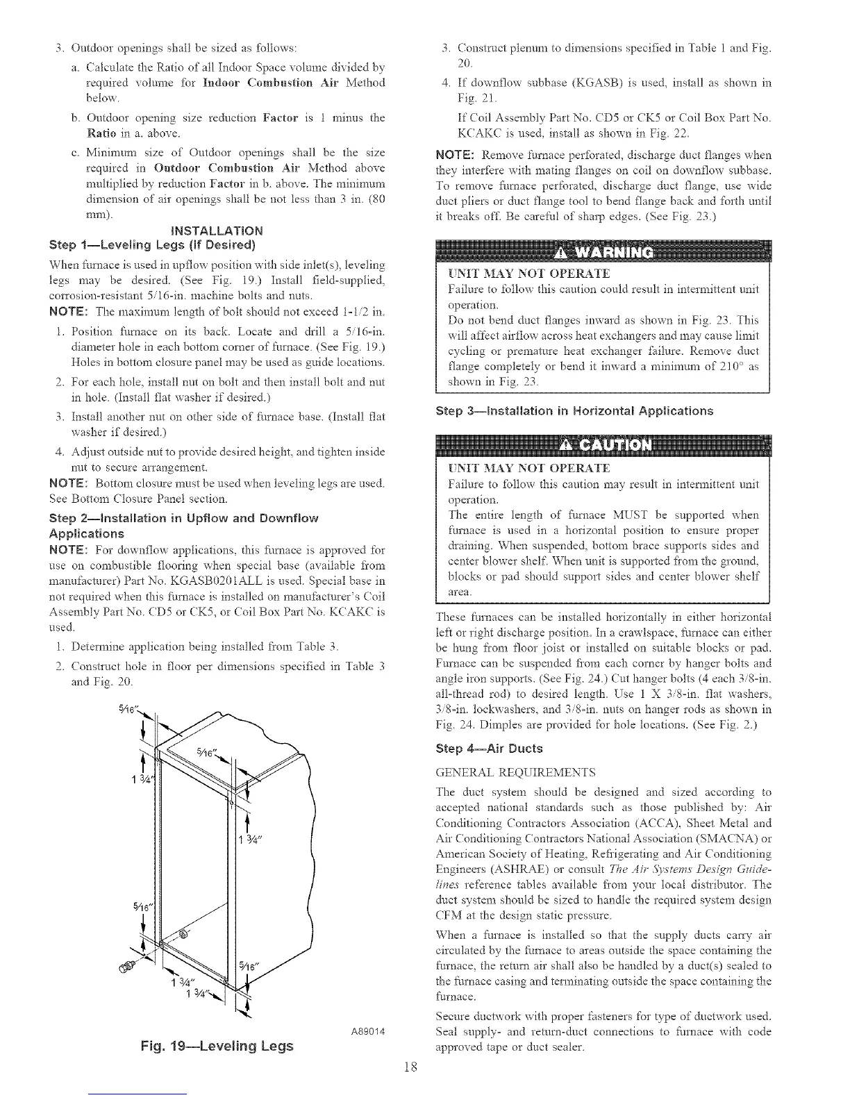
Step l--Leveling Legs (If Desired)
When furnace is used in opflow position with side inlet(s), leveling
legs may be desired. (See Fig. 19.) Install field-supplied,
corrosion-resistant 5/16-im machine bolts and nuts.
NOTE: The nlaximmll length of bolt should not exceed 1- 1/2 in.
1. Position flmaace on its back. Locate and drill a 5/16=in.
diameter hole in each bottom corner of furnace. (See Fig. 19.)
Holes in bottom closure panel may be used as guide locations.
2. For each hole. install nut on bolt and then install bolt and nut
in hole. (Install flat washer if desired.)
3. Install another nut on other side of fl/mace base. (Install flat
washer if desired.)
4. Adjust outside nut to provide desired height, and tighten inside
nut to secure arrangement.
NOTE: Bottom closure must be used when leveling legs are used
See Bottom Closure Panel section
Step 2--_nstaHation in Upfiow and Downflow
Applications
NOTE: For downflow applications, this fhrnace is approved for
use on combustible flooring when special base (available fl'om
manufacturer) Part No. KGASB0201ALL is used. Special base in
not required when dlis fhmace is installed on manufacturer's (?oil
Assenlbly Part No. CD5 or CK5, or (;oil Box Part No. KCAKC is
used,
1. Determine application being installed from Table 3.
2. (onstruct hole in floor per dimensions specified in Table 3
and Fig. 20.
Fig, 19--Leve{ing Legs
A89014
18
3. (onstruct plenum to dimensions specified in Table 1 and Fig.
20.
4. If downflow subbase (KGASB) is used, install as shown in
Fig. 2!.
If (oil Assembly Part No. CD5 or CK5 or Coil Box Part No
KCAKC is used, install as shown in Fig. 22.
NOTE: Remove t:umace perR_rated, discharge duct flanges when
they interfere with mating flanges on coil on downflow subbase.
To remove fi/rnace perforated, discharge duct flange, use wide
duct pliers or dtlct flange tool to bend flange back and forth until
it breaks off_ Be carefld of sharp edges. (See Fig. 23.)
UNIT MAY NOT OPERATE
Failure to follow this caution could result in intermittent unit
operation.
Do not bend duct flanges inward as shown in Fig 23 This
will affect airflow across heat exchangers arid may cause limit
cycling or premature heat exchanger fifilure. Remove duct
flange completely or bend it inward a nlininlnm of 2!0 ° as
shown in Fig, 23
Step 3--hstaHation in Horizontal Applications
tNIT MAY NOT OPERATE
Failure to %llow tllis caution may result in intermittent unit
operation.
The entire length of flmlace MUST be supported when
furnace is used in a horizontal position to ensure proper
draining. When suspended, bottom brace supports sides and
center blower shelf When unit is supported fi'om file ground,
blocks or pad should support sides and center blower shelf
area.
These furnaces can be installed horizontally in either horizontal
left or right discharge position. In a crawlspace, fmnace can either
be hung from floor joist or installed on suitable blocks or pad.
Furnace can be suspended flora each corner by hanger bolts and
angle iron supports. (See Fig. 24.) (Jut hanger bolts (4 each 3i8=im
all=thread rod) to desired length. Use 1 X 3i8=im flat washers.
3/%in. lockwashers, and 3/8=in. nuts on hanger rods as shown in
Fig. 24. Dimples are provided for hole locations. (See Fig. 2.)
Step 4-==Air Ducts
GENERAL REQUIREMENTS
The duct system should be designed and sized according to
accepted national standards such as those published by: Air
Conditioning Contractors Association (ACCA), Sheet Metal arid
Air Conditioning ContIactors National Association (SMACNA) or
American Society- of Heating, Refrigerating and Air Conditioning
Engineers (ASHRAE) or consult The Ai_' 5)',slems DesNr_ Gzdde-
[i_ves refkrence tables available fi'om your local distributor. The
duct system should be sized to handle the required system design
CFM at the design static pressure.
When a furnace is installed so that the supply ducts caia T air
circulated by the furnace to areas outside _he space containing the
Nrnace, the remm air shall also be handled by a duct(s) sealed to
the furnace casing and temlinating outside the space containing the
furnace
Secure ductwork with proper fasteners for type of ductwork used.
Seal supply° and return-duct connections to furnace with code
approved tape or duct sealer.
 Loading...


