UNIT MAY NOT OPERATE
Failure to follow this caution may result in intermittent unit
operation.
Furnace control must be grounded for proper operation or
control will lock out. Control is grounded through
green/yellow wire routed to gas valve C-terminal and burner
box screw.
115-V WIRING
Before proceeding with electrical connections, make certain that
voltage, frequency, and phase correspond to that specified on the
furnace rating plate. Also, check to be sure that service provided
by power supply is sufficient to handle load imposed by this
equipment. Refer to rating plate or Table 4 for equipment electrical
specifications.
For U.S. installations, make all electrical connections in accor-
dance with National Electrical Code (NEC) ANSI/NFPA 70-2002
and any local codes or ordinances that might apply. For Canadian
installations, all electrical connections must be made in accordance
with Canadian Electrical Code CSA C22.1 or authorities having
jurisdiction.
Use a separate branch electrical circuit containing a properly sized
fuse or circuit breaker for this furnace. See Table 4 for wire size
and fuse specifications. A disconnecting means must be located
within sight from and readily accessible to furnace.
NOTE: Proper polarity must be maintained for 115-v wiring. If
polarity is incorrect, control LED status indicator light will flash
rapidly and furnace will NOT operate.
FIRE HAZARD
Failure to follow this warning could result in intermittent
operation or performance satisfaction.
Do not connect aluminum wire between disconnect switch
and furnace. Use only copper wire. (See Fig. 29.)
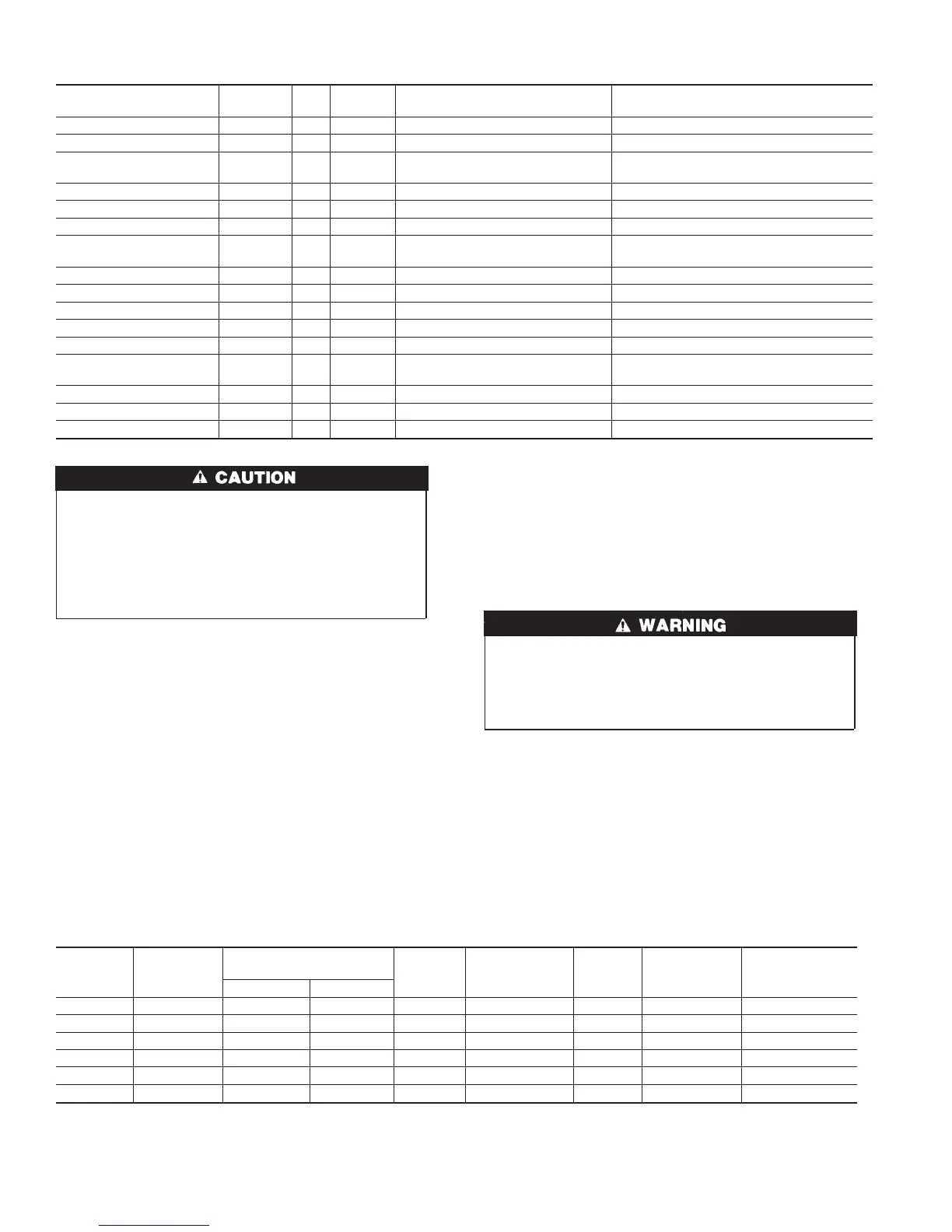
Table 4—ELECTRICAL DATA
UNIT
SIZE
VOLTS—
HERTZ—
PHASE
OPERATING
VOLTAGE RANGE
MAX
UNIT
AMPS
UNIT
AMPACITY†
MIN
WIRE
SIZE
MAX WIRE
LENGTH
(FT)‡
MAX FUSE
OR CKT BKR
AMPS**
Max* Min*
060–12 115-60-1 127 104 8.4 11.3 14 33 15
080–12 115-60-1 127 104 8.1 10.8 14 34 15
080–16 115-60-1 127 104 11.6 15.3 12 37 20
100–16 115-60-1 127 104 11.6 15.4 12 37 20
100–20 115-60-1 127 104 13.3 17.5 12 33 20
120–20 115-60-1 127 104 12.9 16.8 12 34 20
* Permissible limits of voltage range at which unit will operate satisfactorily.
† Unit ampacity = 125 percent of largest operating component’s full load amps plus 100 percent of all other potential operating components’ (EAC, humidifier, etc.) full
load amps.
‡ Length shown is measured 1 way along wire path between unit and service panel for maximum 2 percent voltage drop.
** Time-delay type is recommended.
Table 5—APPROVED COMBUSTION-AIR AND VENT PIPE, FITTING AND CEMENT MATERIALS
ASTM SPECIFICATION
(MARKED ON MATERIAL)
MATERIAL PIPE FITTINGS SOLVENT CEMENT AND PRIMERS DESCRIPTION
D1527 ABS Pipe — — Schedule-40
D1785 PVC Pipe — — Schedule-40
D2235 For ABS — —
Solvent
Cement
For ABS
D2241 PVC Pipe — — SDR-21 & SDR-26
D2466 PVC — Fittings — Schedule-40
D2468 ABS — Fittings — Schedule-40
D2564 For PVC — —
Solvent
Cement
For PVC
D2661 ABS Pipe Fittings — DWV at Schedule-40 IPS sizes
D2665 PVC Pipe Fittings — DWV
F438 CPVC — Fittings — Schedule-40
F441 CPVC Pipe — — Schedule-40
F442 CPVC Pipe — — SDR
F493 For CPVC — —
Solvent
Cement
For CPVC
F628 ABS Pipe — — Cellular Core DWV at Schedule-40 IPS sizes
F656 For PVC — — Primer For PVC
F891 PVC Pipe — — Cellular Core Schedule-40 & DWV
22
→