ELECTRICAL SHOCK AND FIRE HAZARD
Failure to follow this warning coud result in electrical shock,
fire, or death.
The furnace casing MUST have an uninterrupted or unbroken
ground according to NEC ANSI/NFPA 70-2002 and Cana-
dian Electrical Code CSA C22.1 or local codes to minimize
personal injury if an electrical fault should occur. This may
consist of electrical wire or conduit approved for electrical
ground when installed in accordance with existing electrical
codes. Do not use gas piping as an electrical ground.
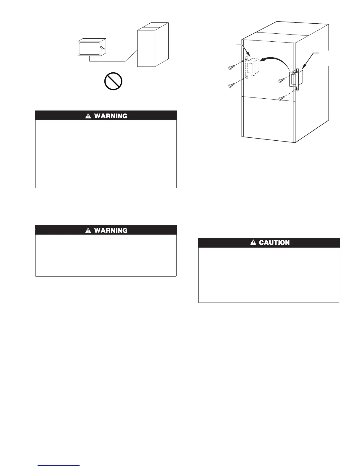
J-BOX RELOCATION
1. Remove 2 screws holding auxiliary J-box. (See Fig. 30.)
2. Rotate J-box 180° and attach box to left side, using holes
provided.
FIRE OR ELECTRICAL SHOCK HAZARD
Failure to follow this warning could result in intermittent unit
operation or performance satisfaction.
If manual disconnect switch is to be mounted on furnace,
select a location where a drill or fastener will not contact
electrical or gas components.
24-V WIRING
Make field 24-v connections at 24-v terminal block on furnace.
(See Fig. 32.) Connect terminal Y/Y2 as shown in Fig. 27 and 28
for proper cooling operation. Use only AWG No. 18, color-coded,
copper thermostat wire for lengths up to 100 ft. For wire lengths
over 100 ft, use AWG No. 16 wire.
The 24-v circuit contains an automotive-type, 3-amp fuse located
on furnace control (See Fig. 32.) Any direct shorts of 24-v wiring
during installation, service, or maintenance could cause this fuse to
blow. If fuse replacement is required, use ONLY a 3-amp fuse of
identical size/type. The control will flash code 24 when fuse needs
replacement.
ACCESSORIES
1. Electronic Air Cleaner (EAC)
Two male quick-connect terminals marked EAC-1 and EAC-2
are provided for EAC connection. (See Fig. 32.) These
terminals are energized with 115-v (1.0-amp maximum)
during blower motor operation.
2. Humidifier (HUM)
Connect an accessory 24 VAC, 0.5 amp maximum humidifier
(if used) to the 1/4-in. male quick-connect HUM terminal and
C
OM-24V screw terminal on the control board thermostat strip.
The HUM terminal is energized when gas valve is energized.
(See Fig. 31 or 32.)
NOTE: A field-supplied, 115–v controlled relay connected to
EAC terminals may be added if humidifier operation is desired
during blower operation.
UNIT DAMAGE HAZARD
Failure to follow this caution may result in unit component
damage.
DO NOT connect furnace control HUM terminal to HUM
(humidifier) terminal on Thermidistat™, Zone Controller or
similar device. See Thermidistat™, Zone Controller, thermo-
stat, or controller manufacturer’s instructions for proper
connection.
Step 9—Direct Venting
The 58MTA furnace requires a dedicated (one 58MTA furnace
only) direct-vent system. In a direct-vent system, all air for
combustion is taken directly from outdoor atmosphere, and all flue
gases are discharged to outdoor atmosphere.
REMOVAL OF EXISTING FURNACES FROM
COMMON VENT SYSTEMS
When an existing Category I furnace is removed or replaced, the
original venting system may no longer be sized to properly vent
the remaining attached appliances. An improperly sized Category
I venting system could cause the formation of condensate in the
furnace and vent, leakage of condensate and combustion products,
and spillage of combustion products into the living space, etc.
Fig. 29—Disconnect Switch and Furnace
A93033
COPPER
WIRE ONLY
ELECTRIC
DISCONNECT
SWITCH
ALUMINUM
WIRE
Fig. 30—Relocating J-Box
A00212
FACTORY
INSTALLED
LOCATION
ALTERNATE
FIELD
LOCATION
23
→
→