UNIT DAMAGE HAZARD
Failure to follow this caution may result in unit component
damage.
Inducer housing outlet cap must be installed and fully seated
against inducer housing. Clamp must be tightened to prevent
any condensate leakage.
c. Install pipe support (factory-supplied in loose parts bag)
into selected furnace casing vent pipe hole. Pipe support
should be positioned at bottom of casing hole.
UNIT DAMAGE HAZARD
Failure to follow this caution may result in unit component
damage.
Vent pipe must be installed and fully seated against inducer
housing internal stop. Clamp must be tightened to prevent any
condensate leakage.
NOTE: A 2-in. diameter pipe must be used within the furnace
casing. Make all pipe diameter transitions outside furnace casing.
d. Be certain that mating surfaces of inducer housing connec-
tion, elastomeric coupling, and 2-in. diameter vent pipe are
clean and dry. Assemble the elastomeric (rubber) vent
coupling (with 2 loose clamps) onto inducer housing
connection. Insert the 2-in. diameter vent pipe through the
elastomeric (rubber) coupling and fully into inducer hous-
ing connection until it bottoms on the internal stop. Tighten
both clamps to secure the pipe to inducer housing. Tighten
the clamp screws to 15 in.-lb. of torque.
e. Install casing hole filler plug (factory-supplied in loose
parts bag) in unused combustion-air pipe casing hole.
Vent Extension Pipe: Furnaces with 100,000 Btuh and larger
inputs are supplied with a PVC vent extension pipe (2-in. diameter
by 12-in. long). This pipe has a built-in channel to assist vent
condensate disposal. When this vent extension pipe is supplied, it
must be used to connect the field vent pipe to furnace inducer
housing on ALL upflow and downflow applications.
NOTE: See label on vent extension pipe for proper installation.
This pipe may be shortened if an elbow is used to connect vent
extension tube to field installed vent pipe.
3. Working from furnace to outside, cut pipe to required
length(s).
4. Deburr inside and outside of pipe.
5. Chamfer outside edge of pipe for better distribution of primer
and cement.
6. Clean and dry all surfaces to be joined.
7. Check dry fit of pipe and mark insertion depth on pipe.
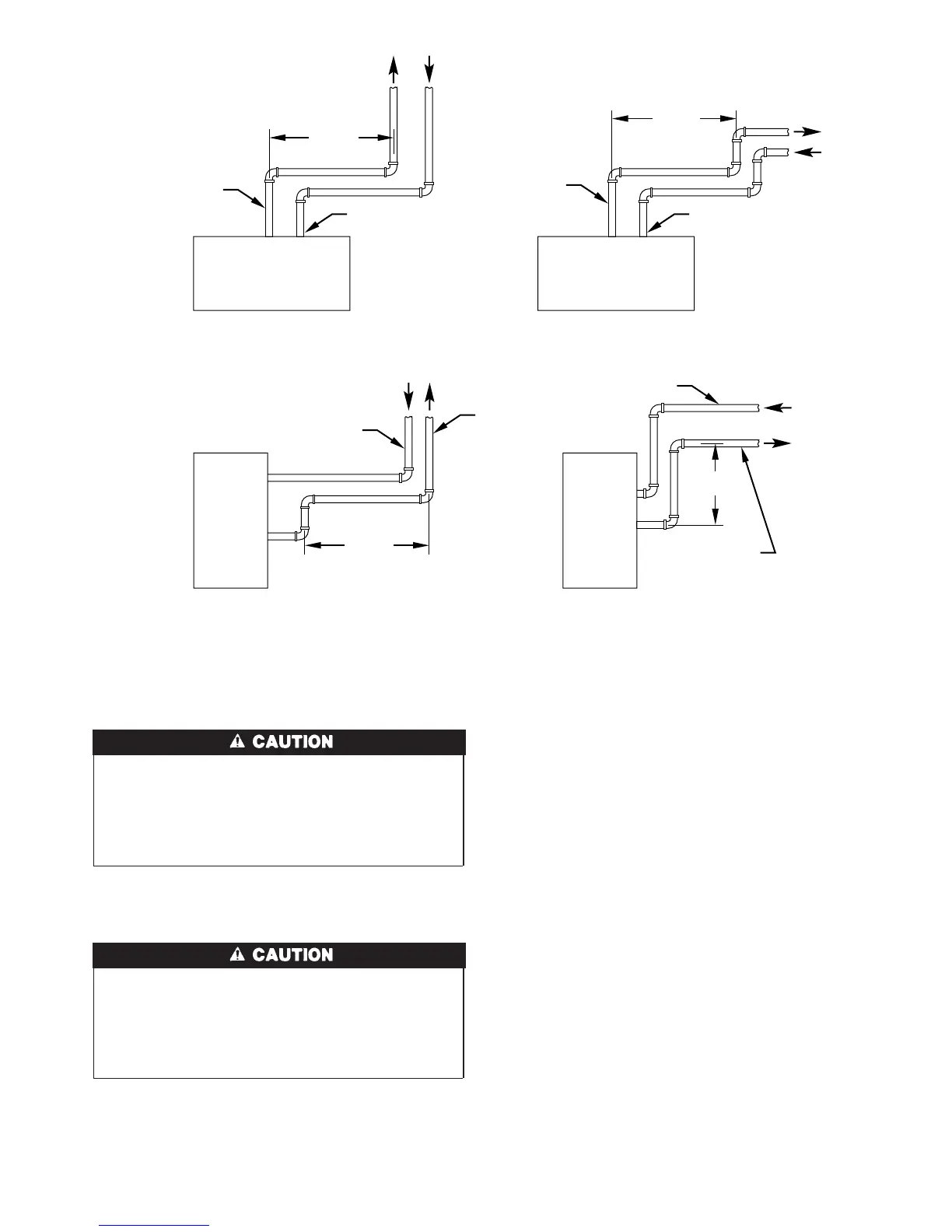
Fig. 35—Short Vent (5 to 8 ft) System
A96230
HORIZONTAL TO ROOF HORIZONTAL TO SIDEWALL
VERTICAL TO SIDEWALLVERTICAL TO ROOF
VENT PIPE
COMBUSTION-AIR PIPE COMBUSTION-AIR PIPE
VENT PIPE
COMBUSTION-AIR PIPE
VENT PIPE
COMBUSTION-AIR PIPE
VENT PIPE
12″ MIN
12″ MIN
12″ MIN
12″ MIN
NOTE: A 12 In. minimum offset pipe section is recommended with
short (5 to 8 ft) vent systems. This recommendation is to reduce
excessive condensate droplets from exiting the vent pipe.
29
→
→