Natural gas service pressure must not exceed 0.5 psig (14-in. wc),
and be no less than 0.16 psig (4.5-in. wc).
Thermostat wire connections at R and W/W1 are the minimum
required for gas heating operation. W2 must be connected for
2-stage heating thermostats. C
OM, Y/Y2, and G are required for
cooling, heat pumps, and some clock thermostats. These must be
made at the 24-v terminal block on the control. (See Fig. 32.)
This furnace can be installed with either a single-stage heating or
a 2-stage heating thermostat.
For single-stage thermostats, connect thermostat W to W/W1 at
furnace control terminal block. (See Fig. 27 and 52H.) For
single-stage thermostats, the control will determine, based on
length of previous heating on and off cycles, when to operate in
low- and high- gas heat for optimum comfort. Setup switch-1
(SW-1) must be in the factory-shipped OFF position. See Fig. 31
and Table 9A and B for setup switch information.
If a 2-stage heating thermostat is to be used, move SW-1 to ON
position at end of furnace installation. This overrides built-in
control process for selecting high and low fire and allows the
TABLE 8—MAXIMUM ALLOWABLE EXPOSED VENT PIPE LENGTH (FT) WITH AND WITHOUT INSULATION IN
WINTER DESIGN TEMPERATURE AMBIENT*
UNIT
SIZE
WINTER DESIGN
TEMPERATURE
(°F)
MAX PIPE
DIAMETER
(IN.)
WITHOUT
INSULATION
WITH 3/8–IN. OR
THICKER INSULATION†
060
20 2 44 70
0 2 21 70
-20 2 20 57
080
20 2 55 55
0 2 30 55
-20 2 16 55
20 2.5 58 70
0 2.5 29 70
-20 2.5 14 67
100
20 2.5 40 40
0 2.5 38 40
-20 2.5 21 40
20 3 63 70
0 3 30 70
-20 3 12 70
120
20 3 70 70
0 3 38 70
-20 3 19 70
20 4 65 70
0 4 26 70
-20 4 5 65
* Pipe length (ft) specified for maximum pipe lengths located in unconditioned spaces. Pipes located in unconditioned space cannot exceed total allowable pipe length
as specified in Table 7.
† Insulation thickness based on R value of 3.5 per in.
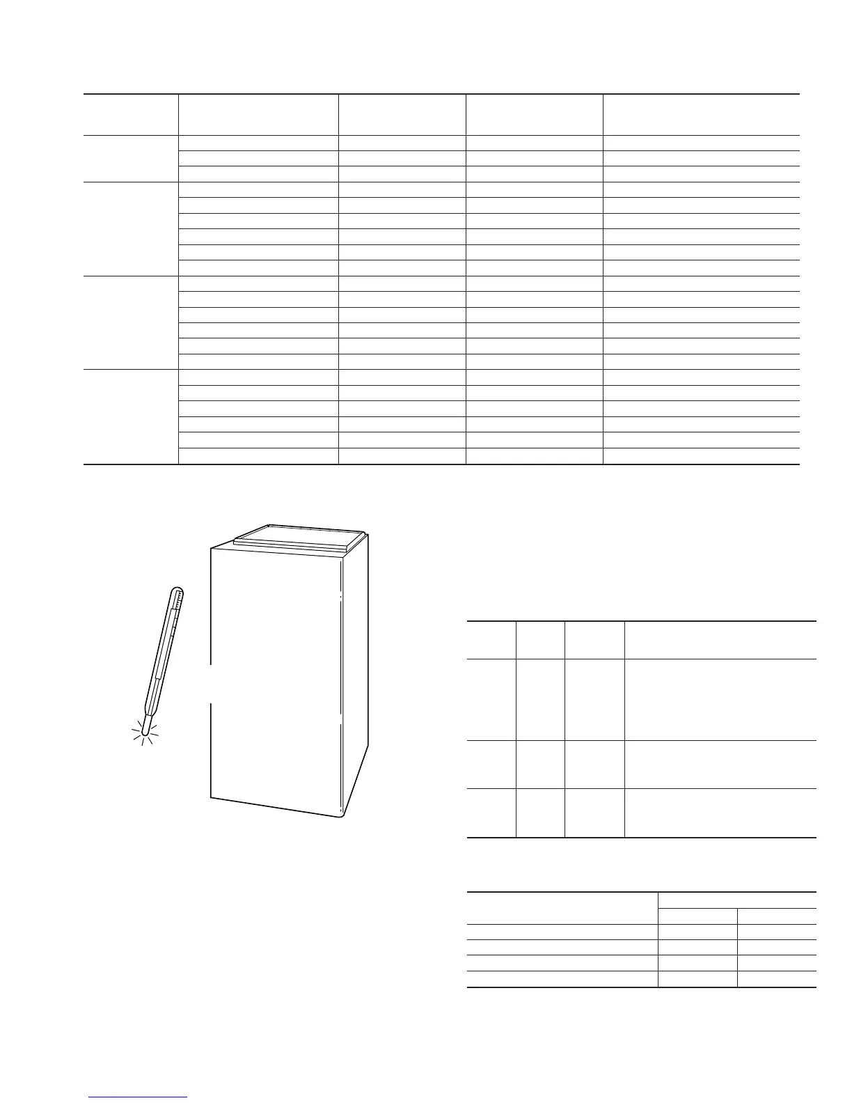
Fig. 42—Freeze Protection
A93058
32
°
F MINIMUM INSTALLED
AMBIENT OR FREEZE
PROTECTION REQUIRED
Table 9A—Furnace Setup Switch Description
SETUP
SWITCH
NO.
SWITCH
NAME
NORMAL
POSITION
DESCRIPTION
OF
USE
SW-1
Adaptive
Heat
Mode
OFF
When off, allows 2-stage operation with a
single-stage thermostat.
Turn on when using 2-stage
thermostat to allow Low Heat
operation when R to W/W1 closes
and High Heat operation when
R to W/W1 and W2 close.
SW-2
Blower
OFF
delay
ON or OFF
Control blower OFF
delay time. Used in
conjunction with SW-3.
See Table 9B.
SW-3
Blower
OFF
delay
ON or OFF
Control blower OFF
delay time. Used in
conjunction with SW-2.
See Table 9B.
Table 9B—Blower Off Delay Setup Switch (SW)
2–Stage Units with PSC Blower Motors
DESIRED HEATING MODE
BLOWER-OFF DELAY (SEC)
SETUP SWITCH
SW-2 SW-3
90 OFF OFF
120 OFF ON
150 ON OFF
180 ON ON
35