UNIT DAMAGE HAZARD
Failure of plastic components may occur.
Do not use ethylene glycol (Prestone II antifreeze/coolant or
equivalent automotive type).
6. Replace drain connection cap and clamp to inducer housing.
7. Replace main furnace door.
8. Propylene glycol need not be removed before restarting
furnace.
WIRING DIAGRAMS
See Fig. 15, 16 and 21 for the Deluxe 4-Way Multipoise Furnace
wiring diagrams.
TROUBLESHOOTING
Use the troubleshooting guide, the status code LED on the furnace
control and the component test to isolate furnace operation
problems.
A more detailed troubleshooting guide is available from your
distributor.
For an explanation of status codes, refer to service label located on
back of main furnace door (See Fig. 20.)
The furnace control stores all status codes for a period of 72 hours,
regardless of 115-v or 24-v power interruption.
NOTE: Removing blower access panel opens blower access
panel door switch and terminates 115-v power to furnace control.
Before removing blower access panel or turning off 115-v power,
look into blower access panel sight glass for current LED status.
1. To retrieve status code, proceed with the following:
NOTE: NO thermostat signal may be present at furnace control
and all blower time delay periods must be completed.
a. Leave 115-v power to furnace turned on.
b. Remove main furnace door.
c. Look into blower access panel sight glass for current LED
status code.
d. Remove blower access panel.
e. Turn setup switch SW1-1 to ON position. (See Fig. 16 or
21 for location.)
f. Manually close blower access panel door switch. Use a
piece of tape to hold switch closed.
ELECTRICAL SHOCK, UNIT MAY NOT OPERATE
HAZARD
Failure to follow this warning could result in electrical shock,
personal injury, or death.
Blower access panel door switch opens 115-v power to
furnace control. No component operation can occur unless
switch is closed. Caution must be taken when manually
closing this switch for service purposes.
g. The AMBER LED will flash the status codes in the order
of occurence. Record status codes until status code 11
flashes (1 short and 1 long).
h. After status code #11 flashes, the status codes will repeat
until setup switch SW1-1 is turned off.
i. Remove tape to release blower access panel door switch
and replace blower access panel.
j. Operate furnace through 1 heat cycle to test for proper
operation and check LED status.
k. If furnace is operating properly and LEDs indicate proper
operation, replace main furnace door.
2. Status codes are erased after 72 hours or they can be manually
erased by performing the following procedure:
a. Leave 115-v power to furnace turned on.
b. Remove main furnace door.
c. Look into blower access panel sight glass for current LED
status code.
d. Remove blower access panel.
e. Turn setup switch SW1-1 to ON position. (See Fig. 16 or
21 for location.)
f. Jumper thermostat terminals R, W/W1, and Y/Y2 on
furnace control.
g. Manually close blower access panel door switch. Use a
piece of tape to hold switch closed.
h. After status code 11 flashes for at least 2 times, remove R,
W/W1, and Y/Y2 jumpers.
i. Turn setup switch SW1-1 to OFF position.
j. Remove tape to release blower access panel door switch
and replace blower access panel.
k. Operate furnace through 1 heat cycle to check for proper
operation and check LED status.
l. If furnace is operating properly and LEDs indicate proper
operation, replace main furnace door.
3. The control can also assist in troubleshooting by performing a
Component Test. The Component Test will functionally
operate all furnace components, except the gas valve.
NOTE: The component test feature will not operate if the furnace
control is receiving any thermostat signals or until all time delays
have expired.
a. To initiate Component Test proceed with the following:
(1.) Leave 115-v power to furnace turned on.
(2.) Remove main furnace door.
(3.) Remove blower access panel.
(4.) Turn setup switch SW1-6 to ON position.
(5.) Manually close blower access panel door switch. Use
a piece of tape to hold switch closed.
b. When items (1) through (5) above have been completed,
the following will occur:
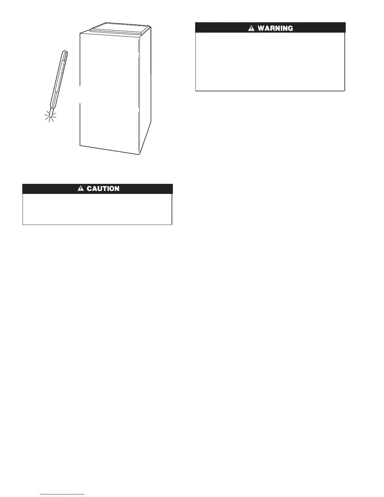
Fig. 17—Freeze Protection
A93058
32°F MINIMUM INSTALLED
AMBIENT OR FREEZE
PROTECTION REQUIRED
12
→

 Loading...


