68
e. Determine reason low pressure switch did not function
properly and correct condition.
f. Turn of f 115--v power to furnace.
g. Reconnect inducer motor wires, replace door, and turn on
115-- v power.
h. Blower will run for 90 sec before beginning the call for
heat again.
i. Furnace should ignite normally.
Checklist
1. Put away tools and instruments. Clean up debris.
2. Verify that the jumper is removed from the TEST/TWIN
terminal. Verify that there is nothing plugged into the PLT
connector. (Note: If there is a jumper connector plugged
into PLT, remove it and discard.) See Fig. 38.
3. Verify that the Blower/Heat Off Delay jumpers are set as
desired. See Fig. 38 and 72.
4. Verify that the blower (lower door in upflow position) and
control (“Main” or upper door in upflow position) doors are
properly installed.
5. Verify that the Status LED glows. If not, check that the
power supply is energized and that the blower door is
secure. See Fig. 63 to interpret diagnostic codes.
6. Cycle test furnace with room thermostat to be sure that it
operates properly with the room thermostat. Check all
modes including Heat, Cool and Fan.
7. Check operation of accessories per manufacturer’s
instructions.
8. Review Owner’s Manual with owner.
9. Attach entire literature packet to furnace.
Table 19 – Altitude Derate Multiplier for U.S.A.
ALTITUDE
PERCENT
OF
DERATE
DERATE
MULTIPLIER
FACTOR*
FT. M
0–2000 0 --- 6 1 0 0 1.00
2001–3000 610---914 4 --- 6 0.95
3001–4000 914---1219 6 --- 8 0.93
4001–5000 1219---1524 8 --- 1 0 0.91
5001–6000 1524---1829 10---12 0.89
6001–7000 1829---2134 12---14 0.87
7001–8000 2134--- 2438 14--- 16 0.85
8001–9000 2438--- 2743 16--- 18 0.83
9001–10,000 2743---3048 18---20 0.81
*Derate multiplier factors are based on midpoint altitude for altitude range.
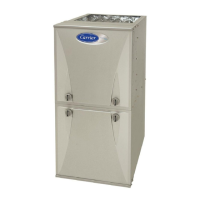
ON/OFF Switch
Regulator Seal Cap
Regulator Adjustment
Regulator Seal Cap under Cap
1/2” NPT Outlet
1/8” NPT Manifold
Pressure Tap
1/8” NPT Inlet
Pressure Tap
1/2” NPT Inlet
SINGLE-STAGE
Representative drawing only, some models may va ry in appea rance.
A11153
Fig. 59 -- Gas Valve without Tower Pressure Ports
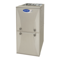
ON/OFF SWITCH
1/8” NPT INLET
PRESSURE TAP
REGULATOR SEAL CAP
(REGULATOR ADJ.
UNDER CAP)
1/2” NPT
OUTLET
MANIFOLD PRESSURE TAP
SET SCREW: 3/32” HEX HEAD
ACCEPTS 5/16” HOSE CONNECTION
OUTP
INP
VENT
1/2” NPT
INLET
INLET PRESSURE
TAP SET SCREW:
3/32” HEX HEAD
ACCEPTS 5/16”
HOSE CONNECTION
Representative drawing only, some models may vary in appearance.
A170118
Fig. 60 -- Gas Valve with Tower Pressure Ports
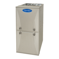
BURNER
ORIFICE
A93059
Fig. 61 -- Orifice Hole
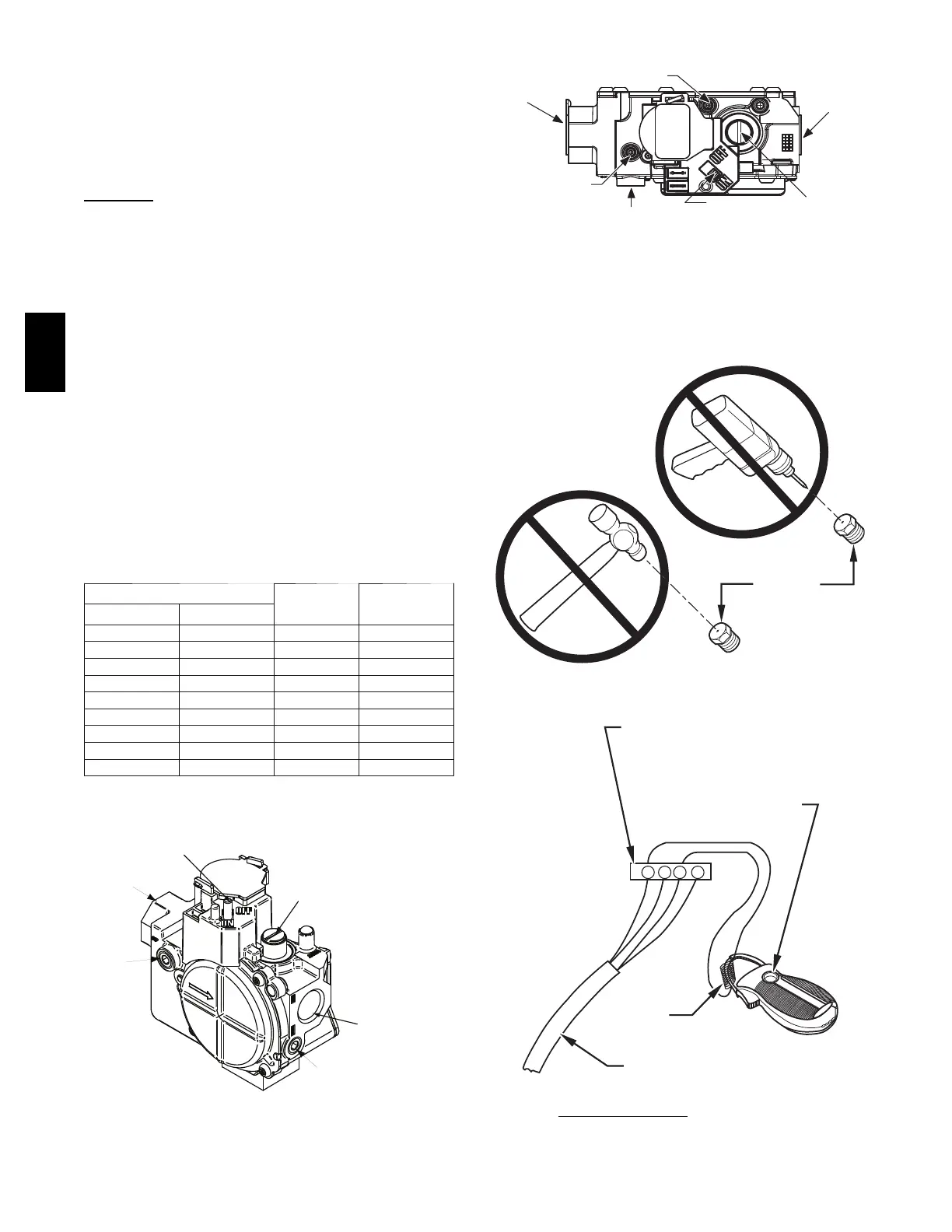
R Y W G
10 TURNS
THERMOSTAT SUBBASE
TERMINALS WITH
THERMOSTAT REMOVED
(ANITICIPATOR, CLOCK, ETC.,
MUST BE OUT OF CIRCUIT.)
HOOK-AROUND
AMMETER
EXAMPLE:
5.0 AMPS ON AMMETER
10 TURNS AROUND JAWS
=
0.5 AMPS FOR THERMOSTAT
ANTICIPATOR SETTING
FROM UNIT 24-V
CONTROL TERMINALS
A96316
Fig. 62 -- Amp. Draw Check with Ammeter
59SP2A