12
CONDENSATE TRAP
Condensate Trap -- Upflow Orientation
When the furnace is installed in the upflow position, it is not
necessary to relocate the condensate trap or associated tubing.
Refer to Fig. 8 for upflow condensate trap information. Refer to
Condensate Drain section for information how to install the
condensate drain.
Condensate Trap -- Downflow Orientation.
When the furnace is installed in the downflow position, the
condensate trap will be initially located at the upper left corner of
the collector box, as received from the factory. See the top image
in Fig. 9. When the furnace is installed in the downflow
orientation, the condensate trap must be relocated for proper
condensate drainage. See the bottom image in Fig. 9.
To Reloca te the Condensate Trap:
S O r ient the fur nace in t he downf l ow posi tion.
S Fig. 9 shows the condensate trap and tubi ng bef or e and after
relocation. Refer to Fig. 9 to begi n the trap conversion.
S Refer to Condensate Dr a in section for information how to ins tall the
condensa t e drain.
Condensate Trap -- Horizontal Orientation.
Whe n the furnace is installed in the hori zontal ri ght posi tion, the
condensa t e t r ap will be initially located at the bottom of the collector
box, as received from the factory . See the top image in Fig. 10.
When the furnace is installed in the horizontal left position, the
condensa t e trap will be initially located at the top of the collector box,
as received from the factory . See the top image in Fig. 11. In both
case s the t rap must be re positioned on the c ollector box for proper
condensa t e drainage . Se e the bott om im a ges in Fi g. 10 and 11.
A field--supplied, accessory Horizontal Installation Kit (trap
grom met) i s re quired for al l dir ect--ve nt horizontal insta l lations (only).
The kit cont ains a rubber casing gr om m et de signed to seal betw een
the furnace casing and the condensa t e trap. See Fig. 17.
The field--supplied, accessory horizontal drain trap grommet is
ONLY REQUIRED FOR DIRECT VENT APPLICATIONS.
It it NOT required for applications using single--pipe or
ventilated combustion air venting.
NOTICE
The condensate trap extends below the side of the casing in
the horizontal position. A minimum of 2--in. (51 mm) of
clearance is required between the casing side and the furnace
platform for the trap to extend out of the casing in the
horizontal position. Allow at least 1/4-- in. per foot (20 mm
per meter) of slope down.
NOTICE
To Reloca te the Condensate Trap:
S Remove t he knockout in the casing for the conde nsate trap.
S Install the grommet in the ca sing when re quired for dir ect--vent
horizontal appl ica t ions.
S Orient the furnace in the desired position.
S A l low for 2 in. (51 mm) of cl earance under neath the fur nace for the
condensa t e trap and drain li ne.
S Fig. 10 shows the condensate trap and tubi ng bef or e and after
relocation in the horizontal right posi tion.
S Fig. 11 shows the condensa t e trap a nd tubing bef ore and after
relocation in the horizontal left position.
S Refer to the appropria te figure to begi n the tr ap conversion.
S Refer to Condensate Dr a in section for information how to ins tall the
condensa t e drain.
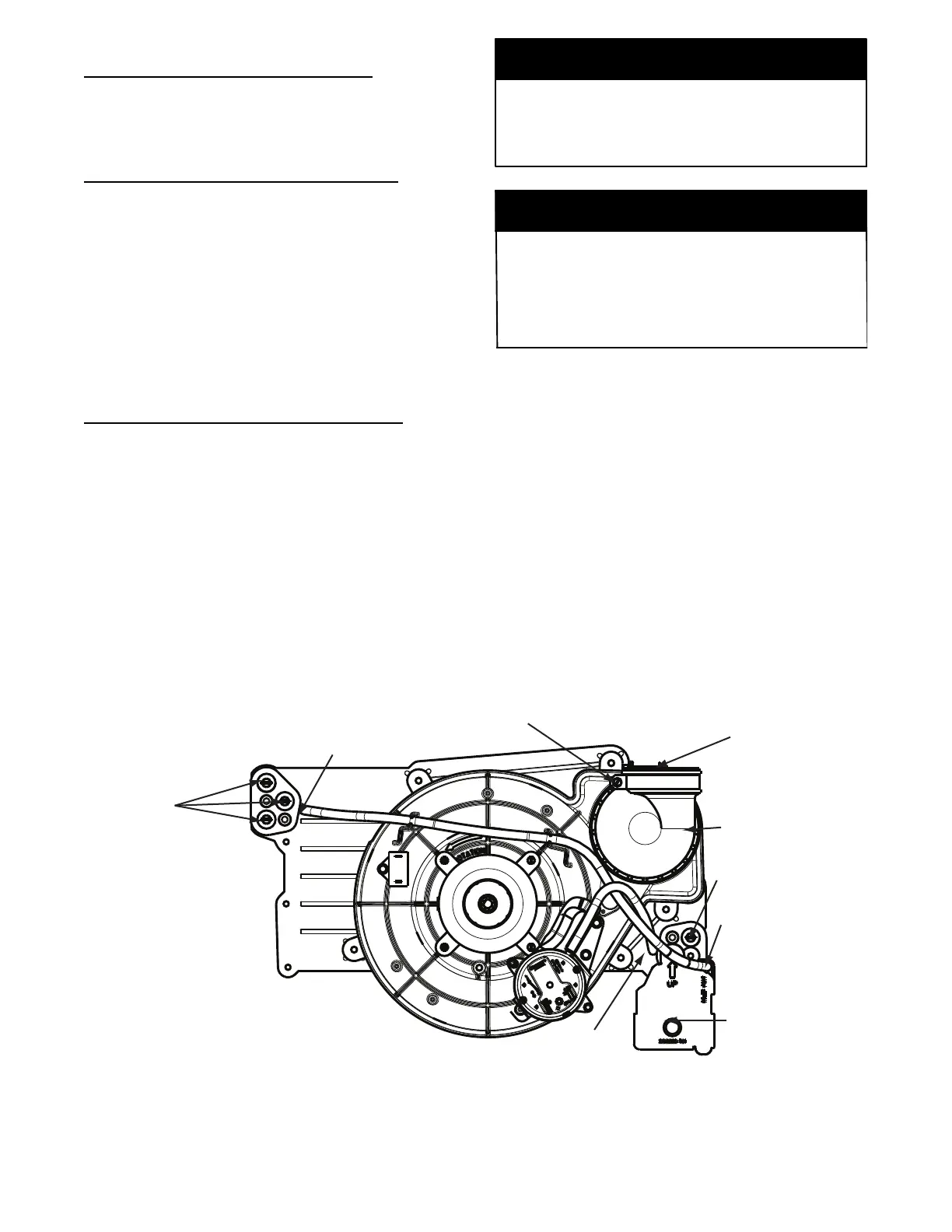
Condensate Trap
Relief Port
Collector Box
Plugs
Pressure Switch
Port
Condensate Trap
Outlet
Condensate Trap
Relief Port
Collector Box
Plug
Vent Elbow
Vent Elbow Clamp
Vent Pipe Clamp
UPFLOW TRAP CONFIGURATION
1 & 2 Stage Units
A11307
Fig. 8 -- Upflo w Trap Configuration
(Appearance may vary)