57
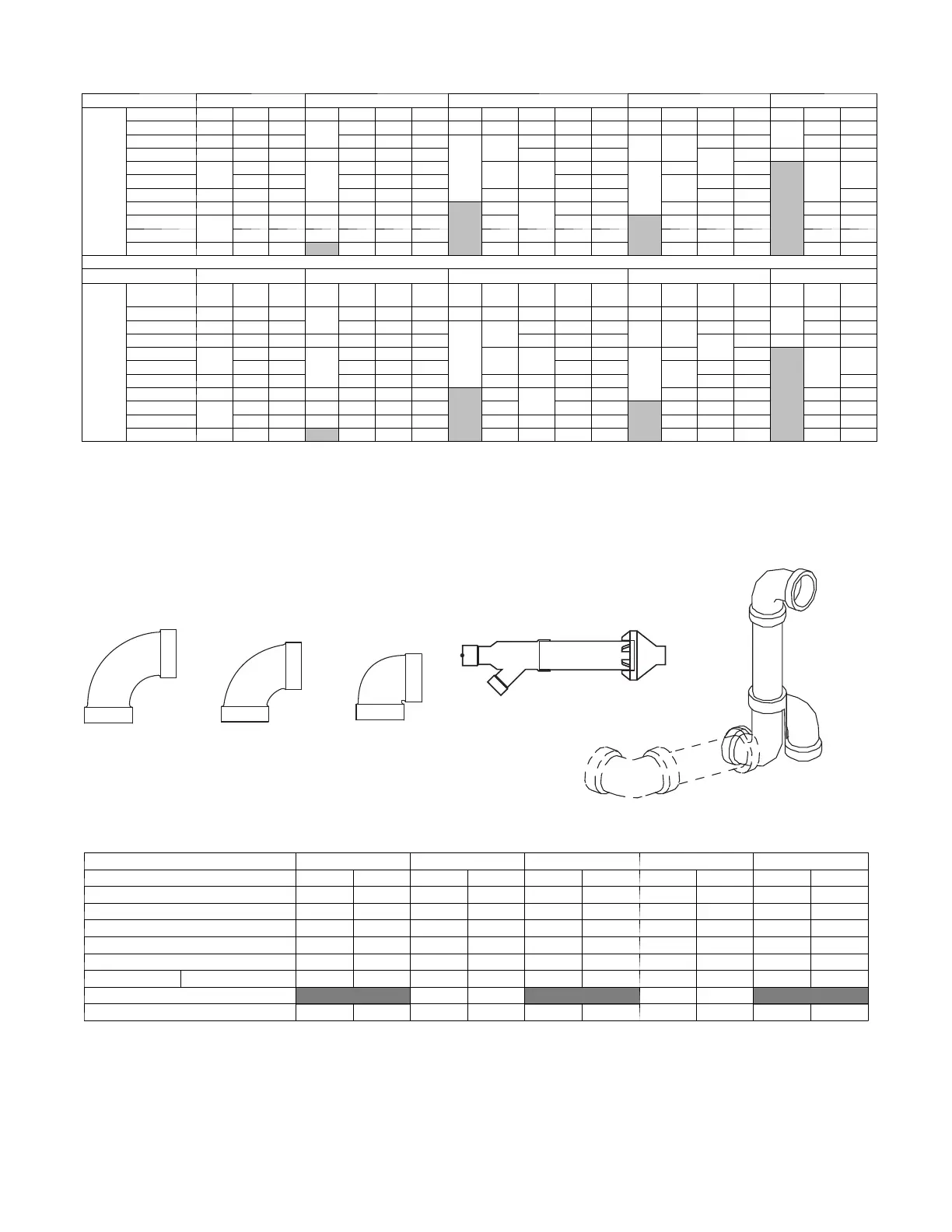
NOTE: Maximum Equivalent Vent Length (MEVL) includes standard a nd concentric vent termination and does NOT include elbows.
Use Table 17 - Deductions from Maximum Equivalent Vent Length to determine allowable vent length for each application.
Table 16 – Maximum Equivalent Vent Length -- Ft.
Unit Size 40,000
1
60,000
2
80,000 100,000
3
120,000
Altitude
(feet)
Pipe Dia. (in) 1½ 2 2½ 1½ 2 2½ 3 1½ 2 2½ 3 4 2 2½ 3 4 2½ 3 4
0--- 2000 40 155 185
20
100 175 200 15 55 130 175 200 20 80 175 200
10
75 185
2001--- 3000 35 150 175 95 165 185
10
49
125 165 185
15 75
165 185 70 175
3001--- 4000 30 135 160 16 90 155 175 115 155 175
155
175 5 65 165
4001--- 4500
25
130 155
15
85 150 170
44 110
150 165
10
70 170
N/A
60
160
4501--- 5000 125 145 80 145 165 145 160
65
150 165
5001--- 6000 20 120 130 75 140 155 41 100 135 150 140 155 155
6001--- 7000 15 110 120 13 70 130 145
N/A
38
90
125 140 60 135 145 50 140
7001--- 8000
10
100 110 10 65 120 135 36 120 125
N/A
55 125 135 46 130
8001--- 9000 90 95 5 60 115 125 33 80 110 115 50 115 125 43 120
9001--- 10000 5 80 85 N/A 55 105 115 30 75 100 105 45 100 115 39 115
Maximum Equivalent Vent Length --- Meters
Unit Size 40,000
1
60,000
2
80,000 100,000
3
120,000
Altitude
(meters)
Pipe Dia.
(mm)
38 51 64 38 51 64 76 38 51 64 76 102 51 64 76 102 64 76 102
0 --- 6 1 0 12.1 47.2 56.3
6.0
30.4 53.3 60.9 4.5 16.7 39.6 53.3 60.9 6.0 24.3 53.3 60.9
3.0
22.8 56.3
611--- 914 10.6 45.7 53.3 28.9 50.2 56.3
3.0
14.9
38.1 50.2 56.3
4.5 22.8
50.2 56.3 21.3 53.3
915--- 1219 9.1 41.1 48.7 4.8 27.4 47.2 53.3 35.0 47.2 53.3
47.2
53.3 1.5 19.8 50.2
1220--- 1370
7.6
39.6 47.2
4.5
25.9 45.7 51.8
13.4 33.5
45.7 50.2
3.0
21.3 51.8
NA
18.2
48.7
1371--- 1524 38.1 44.1 24.3 44.1 50.2 44.1 48.7
19.8
45.7 50.2
1525--- 1829 6.0 36.5 39.6 22.8 42.6 47.2 12.4 30.4 41.1 45.7 42.6 47.2 47.2
1830--- 2134 4.5 33.5 36.5 3.9 21.3 39.6 44.1
NA
11.5
27.4
38.1 42.6 18.2 41.1 44.1 15.2 42.6
2135--- 2438
3.0
30.4 33.5 3.0 19.8 36.5 41.1 10.9 36.5 38.1
NA
16.7 38.1 41.1 14.0 39.6
2439--- 2743 27.4 28.9 1.5 18.2 35.0 38.1 10.0 24.3 33.5 35.0 15.2 35.0 38.1 13.1 36.5
2744--- 3048 1.5 24.3 25.9 NA 16.7 32.0 35.0 9.1 22.8 30.4 32.0 13.7 30.4 35.0 11.8 35.0
NOTES:
1. Inducer Outlet Restrictor disk (P/N 337683 ---401; 1.25---in. (32 mm) Dia.) shipped in the loose parts bag or available th rough Replacement Componen ts
required under 10---ft. ( 3 M) TE V L in al l orientations. Required for installations from 0 --- 2000 (0 to 610 M) above sea level. Failur e to use an outlet restric-
tor may result in flame disturbances or flame sense lock---out.
2. Inducer Outlet Restrictor disk (P/N 337683 ---401; 1.25---in. ( 32 mm) Dia.) available through Replacement Componen ts requ ired for no greater than 5 --- ft . ( 1 . 5
M) TE V L in downfl ow and hor izontal orientations on ly. Required f o r installations from 0 --- 2000 (0 to 610 M) a bove sea level.
3. Inducer Outlet Restrictor disk (P/N 337683 ---402; 1.50---in. ( 38 mm) Dia.) available through Replacement Componen ts requ ired for no greater than 5 --- ft . ( 1 . 5
M) TE V L in downfl ow and hor izontal orientations on ly. Required f o r installations from 0 --- 2000 (0 to 610 M) a bove sea level.
Long
Medium
Mitered
Concentric
Standard 2-in., 3-in., or
optional 4-in. termination.
ELBOW CONFIGURATIONS
VENT TERMINAL CONFIGURATIONS
A13110
Table 17 – Deductions from Maximum Equivalent Vent Length -- Ft. (M)
Pipe Diameter (in): 1-1/2 2 2-1/2 3 4
Mitered 90º Elbow 8 (2.4) 8 (2.4) 8 (2.4) 8 (2.4) 8 (2.4)
Medium Radius 90º Elbow 5 (1.5) 5 (1.5) 5 (1.5) 5 (1.5) 5 (1.5)
Long Radius 90º Elbow 3 (0.9) 3 (0.9) 3 (0.9) 3 (0.9) 3 (0.9)
Mitered 45º Elbow 4 (1.2) 4 (1.2) 4 (1.2) 4 (1.2) 4 (1.2)
Medium Radius 45º Elbow 2.5 (0.8) 2.5 (0.8) 2.5 (0.8) 2.5 (0.8) 2.5 (0.8)
Long Radius 45º Elbow 1.5 (0.5) 1.5 (0.5) 1.5 (0.5) 1.5 (0.5) 1.5 (0.5)
Tee 16 (4.9) 16 (4.9) 16 (4.9) 16 (4.9) 16 (4.9)
Concentric Vent Termination NA 0 (0.0) NA 0 (0.0) NA
Standard Vent Termination 0 (0.0) 0 (0.0) 0 (0.0) 0 (0.0) 0 (0.0)
NOTES:
1. Use only the smallest diameter pipe possible for venting. Over ---sizing may cause flame disturbance or excessive vent terminal icing or freeze ---up.
2. NA --- Not allowed. Pressure switch will not close, or flame disturbance may result.
3. Vent sizing for Can a dian installa tions over 4500 ft. (1370 M) above sea level are subject to acceptance by the local author ities having j urisdiction.
4. Size both the combustion air and vent pipe independently, then use the larger size for both pipes.
5. Assume the two 45_ elbows equal one 90_ elbow. Wide radius elbows are desirable and may be required in some cases.
6. Elbow and pipe sections within the furnace casing and at the vent termination should not be included in vent length or elbow count.
7. The minimum pipe length is 5 ft. (2 M) linear feet (meters) for all applications.
8. Use 3 ---in. (76 mm) diameter vent termination kit for installations requiring 4 ---in. (102 mm) diameter pipe.