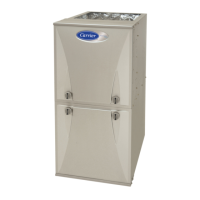
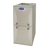
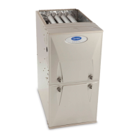
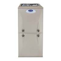
59TP6C: Installation, Start-up, Operating and Service and Maintenance Instructions
Manufacturer reserves the right to change, at any time, specifications and designs without notice and without obligations.
56
SERVICE LABEL
A230315
Fig. 60 – Service Label Information
START-UP, ADJUSTMENT, AND SAFETY
CHECK
General
1. Maintain 115-V wiring and ground. Improper polarity will result in
rapid flashing control diagnostic light and Status code (10.1) is
displayed. The furnace will NOT operate.
2. Make thermostat wire connections at the 24-V terminal block on
the furnace control. Failure to make proper connections will result
in improper operation.
3. Gas supply pressure to the furnace must be greater than 4.5-in. w.c.
(0.16 psig) but not exceed 14-in. w.c. (0.5 psig).
4. Check all manual-reset switches for continuity.
5. Natural gas service pressure must not exceed 0.5 psig (14- in. w.c.,
350 Pa), but must be no less than 0.16 psig (4.5-in. w.c., 1125 Pa).
6. Blower door must be in place to complete 115-V electrical circuit
and supply power to the furnace components.
Start-Up Procedures
1. Purge gas lines after all connections have been made.
2. Check gas lines for leaks.
3. To Begin Component Self-Test
a. Remove thermostat wire connected to R terminal on control to
ensure no thermostat demands are present.
b. Temporarily depress blower door switch to power the control
board to complete component self-test.
CAUTION
!
UNIT OPERATION HAZARD
Failure to follow this caution may result in intermittent unit operation
or performance dissatisfaction.
These furnaces are equipped with a manual reset limit switch in burner
assembly. This switch opens and shuts off power to the gas valve if an
overheat condition (flame rollout) occurs in the burner
assembly/enclosure. Correct inadequate combustion-air supply,
improper gas pressure setting, improper burner or gas orifice
positioning, or improper venting condition before resetting switch. DO
NOT jumper this switch.
NOTICE
!
IMPORTANT INSTALLATION AND START-UP PROCEDURES
Failure to follow this procedure may result in a nuisance smoke or odor
complaint.
The manifold pressure, gas rate by meter clocking, temperature rise and
operation must be checked after installation. Minor smoke and odor
may be present temporarily after start-up from the manufacturing
process. Some occupants are more sensitive to this minor smoke and
odor. It is recommended that doors and windows be open during the
first heat cycle.
CAUTION
!
CUT HAZARD
Failure to follow this caution may result in personal injury.
Sheet metal parts may have sharp edges or burrs. Use care and wear
appropriate protective clothing, safety glasses and gloves when
handling parts and servicing furnaces.
WARNING
!
ELECTRICAL SHOCK HAZARD
Failure to follow this warning could result in personal injury, or death.
Blower access door switch opens 115-V power to control. No
component operation can occur unless switch is closed. Caution must
be taken. Do not touch uninsulated electrical components when
manually closing this switch. for service purposes.
CAUTION
!
SHOCK HAZARD
Failure to follow this caution could result in personal injury.
Do not tape or permanently allow the door switch to be bypassed.
Temporarily depress the door switch with one hand while accessing the
service buttons with your other hand. Do not touch uninsulated
electrical components.
 Loading...
