7
thermostat and snap apart carefully to separate mounting base from re-
mainder of thermostat.
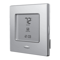
4. Route thermos t at wires through large hole i n mounting base. Level mount i ng
base agai nst wall (for aesthet i c value only— t hermos t at need not be level for
proper operation) and mark wall through four mounting holes. To avoid uni n-
tended bendi ng of wa l l plate pl as t i c, all four screw s and anchors must be used.
See Fig. 1.
A07153
Fig. 1 -- Backplate Mounting
5. Drill four 3/16--in. mounting holes in wall where marked.
6. Secure mounting base to wall with four screws and anchors provided. To
avoid unintended bending of wall plat e plast i c , all four scr ews and anchors must
be used. Make sure all wires extend through hole in mounting base.
 Loading...