OWNER
’
S GUIDE -
Figure 6
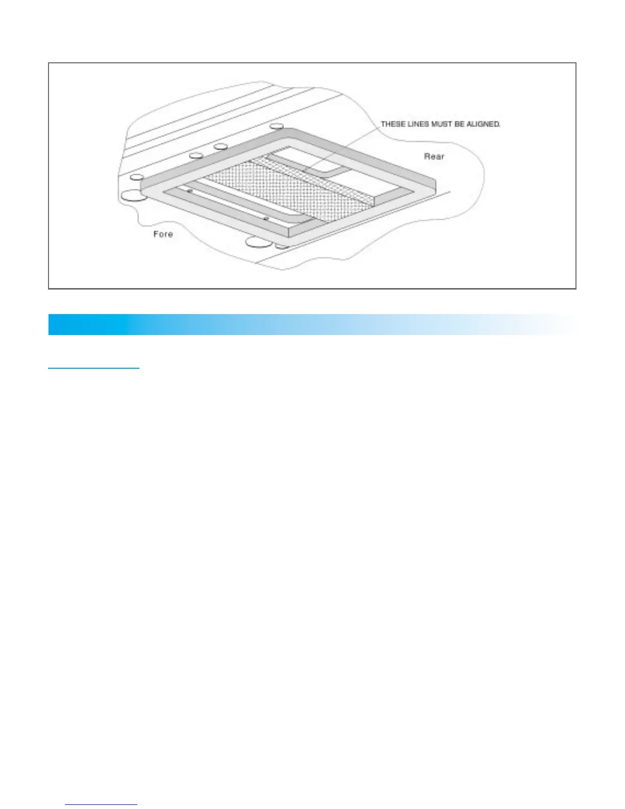
Secure foam topped, three-sided, telescoping divider plate (which is predetermined according to the mea-
sured thickness of the ceiling cavity, refer to p. 10) to the divider plate by tightening two screws, reference
Figure 2 of page 11. The numbers located next to the mounting holes on the telescoping divider plate refer to
the ceiling cavity depth. Install the thin seal divider pad at this time. See Figure 7. Pad is provided with adhesive
on one side with release paper.
Familiarize yourself with the high voltage wiring box, strain relief and wiring. The 115V supply wiring must be
routed through the strain relief in the high voltage wiring box and secured to wiring inside. Extend the three
high voltage wiring box leads and prepare them for attachment to the supply wiring.
A low voltage terminal strip on the front of the box connects to the 12 VDC wires.
13
A. Preparation
1
2
CEILING ASSEMBLY FRAME PREPARATION AND MOUNTING

 Loading...