2
See drawings for unit configurations, dimensions, clearanc-
es, and pipe connections. Refer to unit wiring label for all elec-
trical connections. Follow NEC (National Electrical Code) and
local codes.
INSTALLATION
Step 1 — Unpack and Inspect Unit —
Remove ship-
ping wraps from unit and check shipment against shipping list.
Check for concealed shipping damage. If shipment is damaged
or incomplete, file claim with transportation company and
contact your local Carrier representative immediately.
Step 2 — Protect Unit from Damage — To main-
tain warranty, protect unit against adverse weather conditions,
theft or vandalism on the jobsite.
The described equipment IS NOT suitable for outdoor in-
stallations. The equipment should never be stored or installed
where it may be subjected to a hostile environment such as
rain, snow, or extreme temperatures.
Step 3 — Prepare Jobsite — To save time and to re-
duce the possibility of costly errors, set up a complete sample
installation in a typical room at jobsite. Check all critical di-
mensions such as pipe, wire and duct connection requirements.
Refer to job drawings and product dimension drawings as re-
quired. Instruct all trades in the appropriate part of the installa-
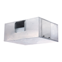
tion. For unit component identification, refer to Fig. 1. For unit
dimensions, refer to Fig. 2 for 42BHE units and Fig. 3 for
42BVE units.
NOTES:
1. All dimensions are in inches (±
1
/
4
in.).
2. Any modifications to product specifications by any person are subject to acceptance of the factory. Product specifications are subject to change without notice.
3. Right hand shown, left hand opposite.
4. Hanger rods, which are field supplied, are shown for reference only.
UNIT
42BHE
DIMENSIONS (in.)
Fan Size Depth Width Height
Supply Duct Return Duct Mounting Holes
ABCDEF J K
06 9 x 4 36 28 19
3
/
4
7
1
/
8
10
1
/
2
14
1
/
2
2
1
/
4
24 16
1
/
2
27
1
/
4
35
1
/
4
08 9 x 6 36 28 19
3
/
4
8
1
/
2
10
1
/
2
13
7
/
8
2
1
/
4
24 16
1
/
2
27
1
/
4
35
1
/
4
10 10 x 4 37
1
/
2
37 21
1
/
2
7
1
/
8
11
9
/
16
15
1
/
4
2
1
/
4
33 18
1
/
4
36
1
/
4
37
12 10 x 7 37
1
/
2
37 21
1
/
2
9
15
/
16
11
9
/
16
13
7
/
8
2
1
/
4
33 18
1
/
4
36
1
/
4
37
16 11 x 10 37
3
/
4
47 21
1
/
2
13
3
/
8
12
3
/
4
16
3
/
4
2
1
/
4
43 18
1
/
4
46
1
/
4
37
20 12 x 9 40
1
/
4
48 24 12
1
/
2
13
3
/
4
17
3
/
4
2
1
/
4
44 20
3
/
4
47
1
/
4
39
1
/
2
30 12 x 12 40
1
/
4
48 32
1
/
4
15
7
/
8
13
3
/
4
16 7
1
/
4
44 29 47
1
/
4
39
1
/
2
40 15 x 12 43
1
/
2
62 32
1
/
4
16
7
/
16
16
1
/
16
22
3
/
4
6
1
/
4
58 29 61
3
/
4
42
1
/
2
Fig. 2 — Unit Dimensions — 42BHE Units
A42-659ef
 Loading...