7
REFRIGERATION CYCLE
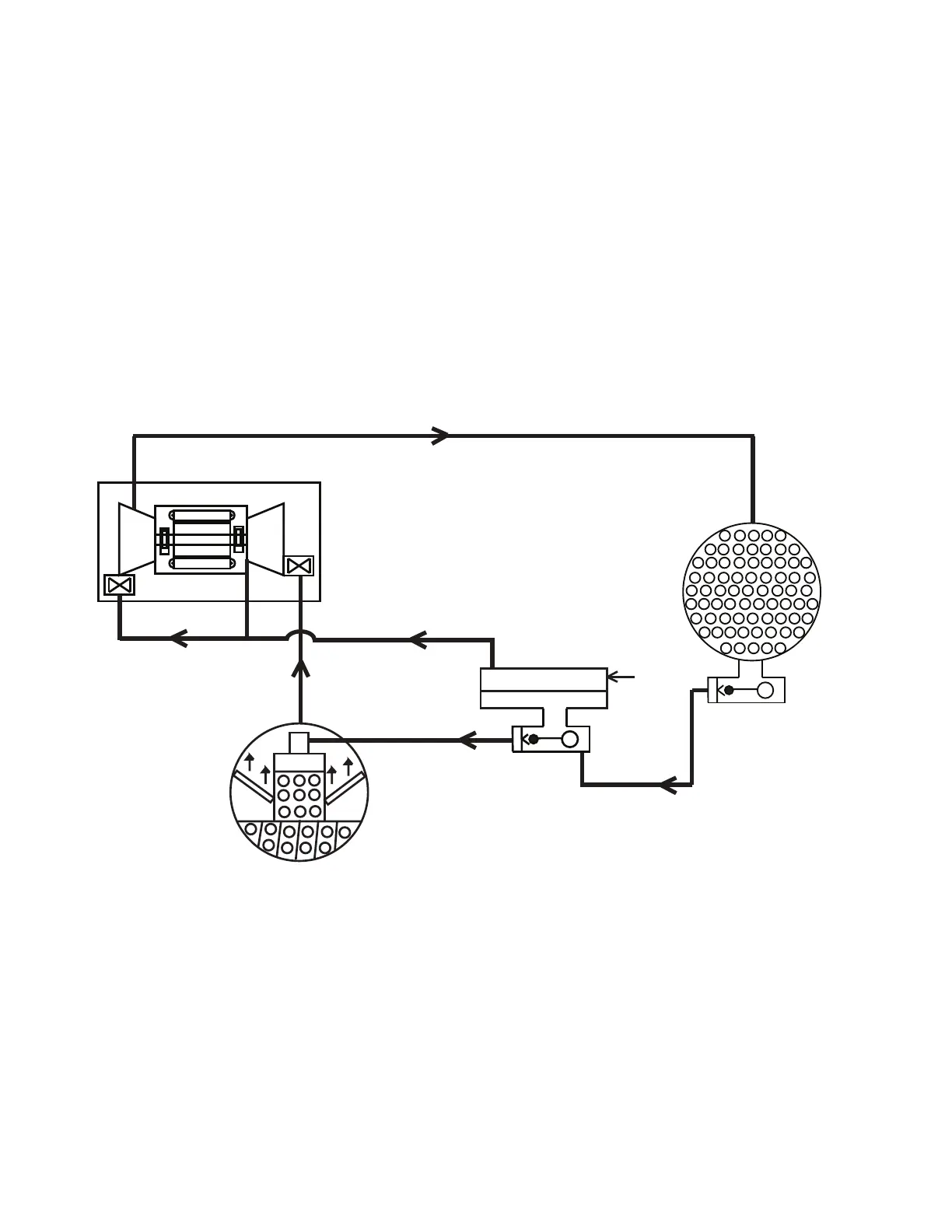
The compressor continuously draws refrigerant vapor from
the evaporator at a rate set by the amount of first stage guide
vane opening and motor speed. As the compressor suction re-
duces the pressure in the evaporator, the remaining refrigerant
boils at a fairly low temperature (typically 38 to 42°F [3 to
6°C]). The energy required for boiling is obtained from the wa-
ter flowing through the evaporator tubes. With heat energy re-
moved, the water becomes cold enough to use in an air-condi-
tioning circuit or process liquid cooling.
After taking heat from the water, the refrigerant vapor is com-
pressed by a back-to-back compression connected by means of
interstage piping. Compression adds heat energy and the refrig-
erant is quite warm (typically 98 to 102°F [37 to 40°C]) when it
is discharged from the compressor into the condenser.
Relatively cool (typically 65 to 90°F [18 to 32°C]) water
flowing into the condenser tubes removes heat from the refrig-
erant, and the vapor condenses to liquid. The liquid drains into
a high side float valve chamber between the condenser and the
economizer. The refrigerant is then metered into the economiz-
er. In the economizer, due to lower pressure, as liquid enters the
chamber, some liquid will flash into a vapor and cool the re-
maining liquid. The separated vapor flows to the second stage
of the compressor for greater cycle efficiency. The second
stage guide vane on the compressor acts as a pressure regulat-
ing device to stabilize operating conditions. At part load the
second stage guide vane will back up gas flow and thereby rais-
es the economizer pressure to allow appropriate refrigerant
flow from economizer to the compressor.
The cooled liquid left in the economizer flows through a
low side float valve and then into the evaporator. The float
valve forms a liquid seal to keep vapor from entering the
evaporator. The refrigerant is now at a temperature and
pressure at which the cycle began. Fig. 3 summarizes the re-
frigeration cycle.
The 19DV unit utilizes R-1233zd(E) refrigerant. At at-
mospheric pressure its boiling point is 65.5°F (18.6°C).
The result is that at normal operating conditions the evapo-
rator typically will be in a vacuum condition and the con-
denser will operate at a pressure above atmospheric pres-
sure. Unit near room temperature will be close to atmo-
spheric pressure.
Fig. 3 — Refrigeration Cycle — 19DV Two-Stage Compressor
HIGH SIDE FLOAT
CHAMBER
COOLER
ECONOMIZER
LOW SIDE
FLOAT CHAMBER
CONDENSER
COMPRESSOR

 Loading...


