EasyManua.ls Logo

Carrier AquaEdge 19XR User Manual

Carrier AquaEdge 19XR
128 pages
To Next Page IconTo Next Page
Page #1 background imageLoading...
Page #1 background image
Manufacturer reserves the right to discontinue, or change at any time, specifications or designs without notice and without incurring obligations.
Catalog No. 04-53190076-01 Printed in U.S.A. Form 19XR-CLT-18SS Rev. A Pg 1 12-21 Replaces: 19XR-CLT-17SS
Start-Up, Operation, and Maintenance
Instructions
CONTENTS
Page
SAFETY CONSIDERATIONS . . . . . . . . . . . . . . . . . . . 2
INTRODUCTION . . . . . . . . . . . . . . . . . . . . . . . . . . . . . . 4
ABBREVIATIONS AND EXPLANATIONS . . . . . . . . . 4
CHILLER FAMILIARIZATION (FIG. 1-5) . . . . . . . . . . . 4
Chiller Information Nameplate . . . . . . . . . . . . . . . . . . 4
System Components . . . . . . . . . . . . . . . . . . . . . . . . . 4
Cooler . . . . . . . . . . . . . . . . . . . . . . . . . . . . . . . . . . . . . . 4
Condenser . . . . . . . . . . . . . . . . . . . . . . . . . . . . . . . . . . 4
Motor-Compressor . . . . . . . . . . . . . . . . . . . . . . . . . . . 4
Control Panel . . . . . . . . . . . . . . . . . . . . . . . . . . . . . . . . 4
Power Panel (19XR2-E) . . . . . . . . . . . . . . . . . . . . . . . . 5
Power Panel (19XR6/7) . . . . . . . . . . . . . . . . . . . . . . . . 5
Economizer (if available) . . . . . . . . . . . . . . . . . . . . . . 5
Free-Standing/Factory-Mounted Starter or VFD . . . 5
Storage Vessel (Optional) . . . . . . . . . . . . . . . . . . . . . 5
REFRIGERATIO
N CYCLE . . . . . . . . . . . . . . . . . . . . . 11
MOTOR AND OIL COOLING CYCLE . . . . . . . . . . . . 12
VFD Cooling Cycle . . . . . . . . . . . . . . . . . . . . . . . . . . 12
LUBRICATION CYCLE
. . . . . . . . . . . . . . . . . . . . . . . 13
Summary . . . . . . . . . . . . . . . . . . . . . . . . . . . . . . . . . . 13
Details . . . . . . . . . . . . . . . . . . . . . . . . . . . . . . . . . . . . 13
Bearings . . . . . . . . . . . . . . . . . . . . . . . . . . . . . . . . . . . 13
Oil Reclaim System . . . . . . . . . . . . . . . . . . . . . . . . . . 13
STARTING EQ
UIPMENT . . . . . . . . . . . . . . . . . . . . . . 16
Unit-Mounted VFDs . . . . . . . . . . . . . . . . . . . . . . . . . . 16
Unit-Mounted Starters . . . . . . . . . . . . . . . . . . . . . . . 16
Solid-State Starter . . . . . . . . . . . . . . . . . . . . . . . . . . . 16
Wye-Delta Starter . . . . . . . . . . . . . . . . . . . . . . . . . . . 16
Free-Standing Starters/VFDs . . . . . . . . . . . . . . . . . . 17
CONTROLS
. . . . . . . . . . . . . . . . . . . . . . . . . . . . . . . . 17
Definitions . . . . . . . . . . . . . . . . . . . . . . . . . . . . . . . . . 17
General . . . . . . . . . . . . . . . . . . . . . . . . . . . . . . . . . . . . 17
PIC 6 System Components . . . . . . . . . . . . . . . . . . . 17
START-UP/SHUTDOWN/
RECYCLE SEQUENCE . . . . . . . . . . . . . . . . . . . . . 19
L
ocal Start/Stop Control . . . . . . . . . . . . . . . . . . . . . . 19
Lubrication Control . . . . . . . . . . . . . . . . . . . . . . . . . . 20
Shutdown . . . . . . . . . . . . . . . . . . . . . . . . . . . . . . . . . . 20
BEFORE INITIAL START-UP . . . . . . . . . . . . . . . . . . 20
Job Data Required . . . . . . . . . . . . . . . . . . . . . . . . . . 20
Equipment Required . . . . . . . . . . . . . . . . . . . . . . . . . 20
Remove Shipping Packaging . . . . . . . . . . . . . . . . . . 20
Open Oil Circuit Valves . . . . . . . . . . . . . . . . . . . . . . 20
Tighten All Gasketed Joints . . . . . . . . . . . . . . . . . . . 21
Check Chiller Tightness . . . . . . . . . . . . . . . . . . . . . .21
Refrigerant Tracer . . . . . . . . . . . . . . . . . . . . . . . . . . .23
Leak Test Chiller . . . . . . . . . . . . . . . . . . . . . . . . . . . .23
Standing Vacuum Test . . . . . . . . . . . . . . . . . . . . . . .23
Chiller Dehydration . . . . . . . . . . . . . . . . . . . . . . . . . .25
Inspect Water Piping . . . . . . . . . . . . . . . . . . . . . . . . .25
Check Relief Valves . . . . . . . . . . . . . . . . . . . . . . . . . .25
Check the Optional Pumpout Compressor Water
Piping . . . . . . . . . . . . . . . . . . . . . . . . . . . . . . . . . . .25
Identify and Check Starter/VFD . . . . . . . . . . . . . . . .25
Mechanical Starter . . . . . . . . . . . . . . . . . . . . . . . . . . .26
Benshaw RediStart MX3 Solid-State Starter . . . . . .26
VFD Starter . . . . . . . . . . . . . . . . . . . . . . . . . . . . . . . . .26
Verify Condition of Installation . . . . . . . . . . . . . . . . .26
Inspect Wiring . . . . . . . . . . . . . . . . . . . . . . . . . . . . . .26
Carrier Comfort Network
®
(CCN) and
Local Equipment Network (LEN) Interface . . . . .27
Check Starter . . . . . . . . . . . . . . . . . . . . . . . . . . . . . . .27
Oil Charge . . . . . . . . . . . . . . . . . . . . . . . . . . . . . . . . . .28
Power Up Controls and Check Oil Heater . . . . . . . .28
Software Configuration . . . . . . . . . . . . . . . . . . . . . . .28
Input the Design Set Points . . . . . . . . . . . . . . . . . . .28
Input the Local Occupied Schedule . . . . . . . . . . . . .28
Input Service Configurations . . . . . . . . . . . . . . . . . .29
Field Set Up and Verification . . . . . . . . . . . . . . . . . .31
Perform a Controls Test (Quick Test/
Quick Calibration) . . . . . . . . . . . . . . . . . . . . . . . . .34
Check Optional Pumpout System Controls and
Compressor . . . . . . . . . . . . . . . . . . . . . . . . . . . . . .34
Charge Refrigerant into Chiller . . . . . . . . . . . . . . . . .34
INITIAL START-UP
. . . . . . . . . . . . . . . . . . . . . . . . . . .37
Preparation . . . . . . . . . . . . . . . . . . . . . . . . . . . . . . . . .37
Check Motor Rotation . . . . . . . . . . . . . . . . . . . . . . . .37
Check Oil Pressure and Compressor Stop . . . . . . .37
To Prevent Accidental Start-Up . . . . . . . . . . . . . . . .37
Check Chiller Operating Condition . . . . . . . . . . . . .37
Instruct the Customer Operator . . . . . . . . . . . . . . . .37
OPERATING INSTRUCTIONS
. . . . . . . . . . . . . . . . . .38
Operator Duties . . . . . . . . . . . . . . . . . . . . . . . . . . . . .38
Prepare the Chiller for Start-Up . . . . . . . . . . . . . . . .38
To Start the Chiller . . . . . . . . . . . . . . . . . . . . . . . . . . .38
Check the Running System . . . . . . . . . . . . . . . . . . .38
To Stop the Chiller . . . . . . . . . . . . . . . . . . . . . . . . . . .38
After Limited Shutdown . . . . . . . . . . . . . . . . . . . . . .38
Preparation for Extended Shutdown . . . . . . . . . . . .38
After Extended Shutdown . . . . . . . . . . . . . . . . . . . . .39
Cold Weather Operation . . . . . . . . . . . . . . . . . . . . . .39
AquaEdge
®
19XR
Single Stage and Two-Stage Semi-Hermetic Centrifugal
Liquid Chillers with PIC 6 Controls and R-134a/R-513A
50/60 Hz

Table of Contents

Other manuals for Carrier AquaEdge 19XR

Question and Answer IconNeed help?

Do you have a question about the Carrier AquaEdge 19XR and is the answer not in the manual?

Carrier AquaEdge 19XR Specifications

General IconGeneral
BrandCarrier
ModelAquaEdge 19XR
CategoryChiller
LanguageEnglish

Summary

Introduction and Chiller Familiarization

Abbreviations and Explanations

Lists and explains frequently used abbreviations in the manual.

Chiller Familiarization (Fig. 1-5)

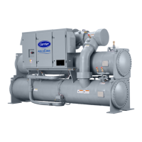
Provides an overview of chiller components and their identification through figures.

System Components

Lists and briefly describes the main components of the chiller system.

Cooler

Describes the cooler (evaporator) function in the refrigeration cycle.

Condenser

Explains the condenser's role in heat removal from refrigerant.

Motor-Compressor

Details the function of the motor-compressor in moving refrigerant.

Control Panel

Outlines the functions of the control panel and its interface.

Power Panel (19XR2-E)

Describes the components within the power panel for 19XR2-E models.

Power Panel (19XR6/7)

Details the power and control components in the power panel for 19XR6/7 models.

Economizer (if available)

Explains the economizer's function in reducing refrigerant pressure.

Free-Standing/Factory-Mounted Starter or VFD

Describes the function of starters and VFDs for compressor operation.

Storage Vessel (Optional)

Lists features of optional storage vessels used for refrigerant.

Refrigeration Cycle Details

Refrigeration Cycle

Explains the compressor operation and refrigerant flow through the chiller.

Fig. 6 — Refrigeration Cycle — 19XR(V) Single-Stage Compressor

Illustrates the refrigeration cycle for single-stage compressors.

Motor and Oil Cooling Cycles

Motor and Oil Cooling Cycle

Describes how liquid refrigerant cools the motor and oil.

Fig. 7 — Refrigeration Cycle — 19XR(V) Two-Stage Compressor

Illustrates the refrigeration cycle for two-stage compressors.

VFD Cooling Cycle

Explains the refrigerant cooling process for unit-mounted VFDs.

Lubrication Cycle Overview

Lubrication Cycle

Details the oil pump, filter, and cooler system components.

Details

Provides detailed information on the oil flow and lubrication system.

Oil Reclaim System

Describes the system for recovering and returning oil to the reservoir.

Starting Equipment and Controls

Starting Equipment

Discusses requirements for motor starters and VFDs.

Unit-Mounted VFDs

Details options for unit-mounted Variable Frequency Drives.

Unit-Mounted Starters

Details the types of unit-mounted starters available.

Solid-State Starter

Explains the function and operation of solid-state starters.

Wye-Delta Starter

Describes the operation of wye-delta starters for low-voltage motors.

Controls

Overview of the microprocessor-based control system and its functions.

General

Describes the chiller control system's monitoring and regulation capabilities.

PIC 6 System Components

Lists and describes the main components of the PIC 6 control system.

Start-Up Procedures

Start-Up/Shutdown/ Recycle Sequence

Details the sequence for starting, stopping, and recycling the chiller.

Local Start/Stop Control

Details how to initiate start-up using the HMI interface.

Before Initial Start-Up

Lists essential job data, equipment, and checks needed before initial start-up.

Tighten All Gasketed Joints

Instructions to tighten all gasketed joints to ensure a leak-tight chiller.

Check Chiller Tightness

Outlines the procedure for checking chiller for leaks.

Leak Determination

Provides methods for determining and testing for refrigerant leaks.

Leak Test Chiller

Provides procedures for performing a leak test on the chiller.

Standing Vacuum Test

Explains how to perform a standing vacuum test for leak detection.

Chiller Dehydration

Recommended procedure if the chiller has been open or contains moisture.

Identify and Check Starter/VFD

Steps to verify the starter/VFD matches documentation and is correctly installed.

Inspect Wiring

Checks to ensure the starter/VFD installation meets requirements.

Check Starter

Verification steps for mechanical starters.

Software Configuration

Guidance on configuring chiller settings via the PIC 6 interface.

Input the Design Set Points

Steps to access and set chiller operating parameters.

Input the Local Occupied Schedule

Instructions for configuring the chiller's time and occupancy schedule.

Field Set Up and Verification

Confirms configuration values match chiller labels and design data.

Surge Prevention

Details parameters and procedures for tuning surge prevention.

Charge Refrigerant into Chiller

Instructions for charging refrigerant into the chiller.

Initial Start-Up

Pre-start verification steps before operating the chiller.

Check Motor Rotation

Procedure to verify correct motor rotation direction.

Check Oil Pressure and Compressor Stop

Steps to check oil pressure and compressor behavior during shutdown.

Operating Instructions

Lists operator duties and procedures for starting and stopping the chiller.

Preparation for Extended Shutdown

Steps to prepare the chiller for extended periods of inactivity.

PUMPOUT AND REFRIGERANT TRANSFER PROCEDURES

Procedures for transferring refrigerant using pumpout systems.

Operating the Optional Pumpout Unit (Fig. 37)

Instructions for operating the optional pumpout unit.

Transfer Refrigerant from Pumpout Storage Tank to Chiller

Procedures for transferring refrigerant from storage tank to chiller.

Return Refrigerant to Normal Operating Conditions

Steps to return refrigerant to normal operating conditions after service.

General Maintenance Procedures

General Maintenance

Covers refrigerant properties, adding, adjusting, and leak testing.

Refrigerant Leak Testing

Methods and importance of testing for refrigerant leaks.

Weekly Maintenance

Tasks to perform weekly for chiller upkeep.

Check the Lubrication System

Procedures for checking the oil level and system operation.

Changing Oil Filter

Steps for safely changing the oil filter.

Inspect Refrigerant Float System

Inspection of the refrigerant float system for proper operation.

Inspect Relief Valves and Piping

Guidance for inspecting and maintaining relief valves and associated piping.

Compressor Bearing and Gear Maintenance

Maintenance procedures for compressor bearings and gears.

Inspect the Heat Exchanger Tubes and Flow Devices

Steps for inspecting and cleaning cooler and condenser tubes.

Inspect the Starting Equipment or VFD

Checks for proper installation and condition of starters and VFDs.

Recalibrate Pressure Transducers

Procedure for recalibrating pressure transducers annually.

Troubleshooting and Diagnostics

Troubleshooting Guide

Overview of the PIC 6 system's troubleshooting features.

Checking Display Messages

How to interpret status and alarm messages on the HMI.

Checking Temperature Sensors

Methods for checking the accuracy of temperature sensors.

Checking Pressure Transducers

Procedures for checking and calibrating pressure transducers.

High Altitude Locations

Adjustments needed for chillers at high altitudes.

Quick Test

Using the quick test feature for diagnostics.

Appendices and Checklists

Appendix A — PIC 6 Screen and Table Structure

Visual representation of the PIC 6 menu navigation structure.

Appendix B — CCN Communication Wiring for Multiple Chillers (Typical)

Wiring details for CCN communication between multiple chillers.

Appendix C — Maintenance Summary and Log Sheets

Recommended maintenance schedule based on time intervals.

Initial Start-Up Checklist

A checklist for verifying all necessary steps are completed before initial start-up.

Check Oil Level and Record:

Section for recording oil level, pressure drops, and electrical data.

CONTROLS: SAFETY, OPERATING, ETC.

Final checks on controls, safety features, and operating procedures.

Related product manuals