114
FIELD-SUPPLIED
FUSED DISCONNECT
CONTROL POWER
FIELD-SUPPLIED
FUSED DISCONNECT
UNIT POWER
AIRFLOW
DRAIN SHUTOFF VALVE
STRAINER*
ISOLATION
VALVE*
PUMP
PRESSURE/
TEMPERATURE
TAPS *
VIBRATION
ELIMINATORS*
BALANCING VALVE/
SHUTOFF*
NOTES:
1. Chiller must be installed level to maintain proper
compressor oil return and hydraulics.
2. Wiring and piping shown are general points-of-
connection guides only and are not intended for a
specific installation. Wiring and piping shown are
for a quick overview of system and are not in
accordance with recognized standards.
3. All wiring must comply with applicable local and
national codes.
4. All pipin
g must follow standard piping techniques.
Refer to Carrier System Design Manual or appro-
priate ASHRAE (American Society of Heating,
Refrigerating, and Air-Conditioning Engineers)
handbook for details.
5. Air separator required as close to chiller as possi-
ble (except primary/secondary systems).
6. 20 mesh strainer required within 10 ft (3 m) of the
cooler in addition to suction strainer for open loop
syst
ems.
LEGEND
*Field-installed.
Airflow Through Condenser
Power Wiring
Chilled Water Piping
A30-4459
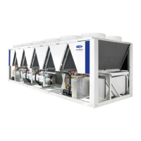
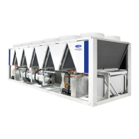
Fig. 37B — 30XA Flooded Cooler Typical Piping and Wiring (Units with Hydronic Package)

 Loading...


