34
NOTES:
1. Unit must have clearances as follows:
Top — Do not restrict
Sides and Ends — 6 ft (1.8 m) from solid surface.
2. Temperature relief devices are located on liquid line and economizer
assemblies and have
1
/
4
-in. flare connection.
3.
3
/
8
-in. NPT vents and drains located in each cooler head at each end of
cooler.
4. Drawing depicts unit with single point power, standard two-pass cooler
standard SCCR (Sho
rt Circuit Current Rating), and nominal voltage
range of 380 to 575 v. Refer to the Packaged Chiller Builder program
for other configurations.
5. Dimensions are shown in inches. Dimensions in [ ] are in millimeters.
30XA UNIT A B
220 46.17 [1173] 171.42 [4354]
240 46.23 [1174] 170.83 [4339]
a30-5210
[162]
[397]
A
[1528]
[1782]
[2236]
[508]
[860]
[508]
[4799]
[4260]
[8363]
[6147]
[5706]
B
[2758]
[4343]
[2438]
[114]
TOP VIEW
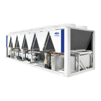
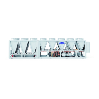
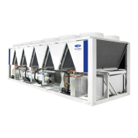
Fig. 13 — 30XA220,240 Air-Cooled Liquid Chiller Dimensions (See Note 4)

 Loading...


