39
MAIN POWER ENTRY
STANDARD SHORT CIRCUIT CONTROL OPTION 200, 230V
HIGH STANDARD SHORT CIRCUIT CONTROL OPTION 460 AND 575V
a30-5484
NEXT PAGE
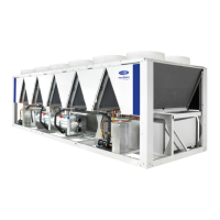
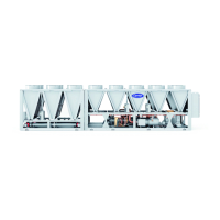
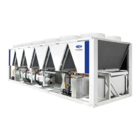
Fig. 14 — 30XA222,242 Air-Cooled Liquid Chiller Dimensions
a30-5484
NOTES:
1. Unit must have clearances as follows:
Top — Do not restrict
Sides and End — 6 ft from solid surface for airflow.
Side — 8 ft required for surface area.
For clearance between multiple units refer to product
data in the Application Data section.
2. Temperature relief devices are located on liquid line and
economizer assemblies and hav
e
1
/
4
-in. flare connection.
3. Pressure relief devices are located on the cooler (
5
/
8
-in.
NPT male connector) and on each oil separator (
3
/
8
-in.
flare connection).
4. Dimensions are shown in inches. Dimensions in [ ] are in
millimeters.
30XA UNIT CGx CGy
222 157.73 [4006] 46.17 [1173]
242 158.32 [4021] 46.23 [1174]

 Loading...


