7
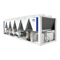
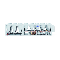
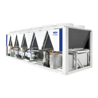
Fig. 3 — 30XA082 Air-Cooled Liquid Chiller Dimensions
30XA UNIT CGx CGy
082 68.5 [1739.9] 35.3 [896.6]
a30-5530
NOTES:
1. Unit must have clearances as follows:
Top — Do not restrict
Sides and Ends — 6 ft (1.8 m) from solid surface
Airflow Side — 8 ft (2.4 m) required for coil service area.
2. Temperature relief devices are located on liquid line and economizer
assemblies and have
1
/
4
-in. flare connection.
3. Pressure relief devices are located on the cooler (
5
/
8
-in. NPT male connector)
and on each oil separator (
3
/
8
-in. flare connector).
4. Dimensions are shown in inches. Dimensions in [ ] are in millimeters.

 Loading...


