24
The optional hydronic modules are not compatible with open loops.
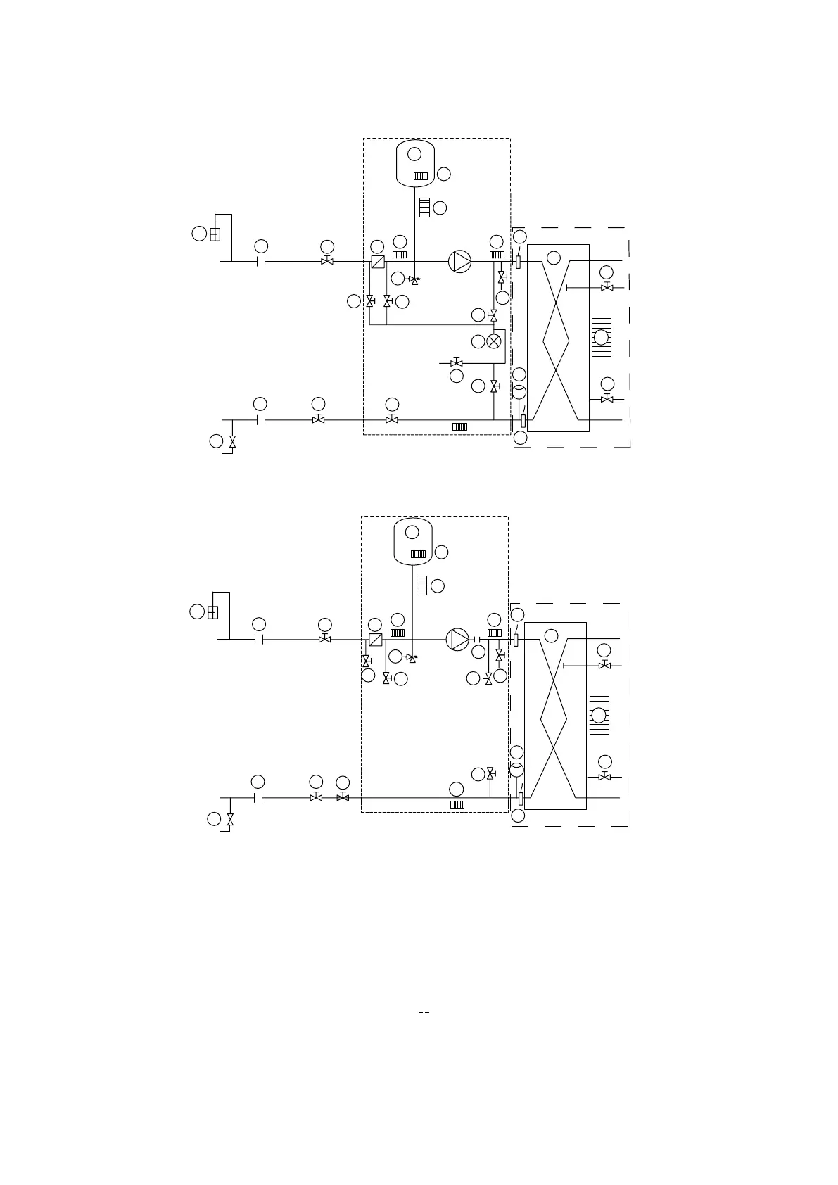
8.2.1 - Unit equipped with hydronic module options 116B, 116C, 116F, 116G
1 Victaulic screen lter
2 Expansion tank
3 Safety valve
4 Available pressure pump
5 Pressure tap - see installation manual
6 Pressure gauge to measure the component pressure drop (if options 116B,
116C, 116F, 116 G are used) - see installation manual
7 Pressure gauge system drain valve (if options 116B, 116C, 116F, 116 G are
used)
8 Drain valve
9 Flow control valve
10 Heat exchanger
11 Evaporator defrost heater
12 Hydronic module defrost heater (option)
13 Air vent (evaporator)
14 Water drain (evaporator)
15 Expansion compensator (exible connections)
16 Flow switch
17 Water temperature
18 Air vent
19 Flexible connection
20 Shut-o valve
21 Charge valve
22 Anti-vibration mounting
23 Pump support
24 Evaporator inlet
25 Evaporator outlet
26 Customer water inlet connection
27 Customer water outlet connection
--- Hydronic module (unit with hydronic module)
Limit of items supplied, chiller environment
B Only for sizes 302-522
- The system is protected against frost (anti-freeze solution or electric heater).
- With option 42A the hydronic module is protected against frost by electric
heaters (item 12).
- The unit evaporator is protected against frost by a factory-installed electric
heater (‘evaporator frost protection’ option)
8.2.2 - Unit equipped with hydronic module options 116M, 116N, 116P, 116Q
1
2
3
4
5
5
6
7
9
20
19
21
12
12
12
14
13
16
5
5
8
18
17
17
12
12
19
10
11
20
1
2
3
4
9
20
19
21
12
12
12
14
13
16
8
18
17
17
12
12
19
10
11
20
15
5
5
5
5
 Loading...