49
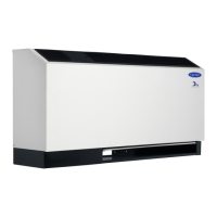
Console Water Source Heat Pumps
HVAC Guide Specifications
Size Range: 8,600 to 16,200 Btuh
Cooling Capacity
11,400 to 20,100 Btuh
Heating Capacity
Carrier Model Number: 50PEC
Part 1 — General
1.01 SYSTEM DESCRIPTION
A. Install water source heat pumps, as indicated on the
plans with capacities and characteristics as listed in
the schedule and the specifications that follow.
B. Units shall be individually packaged with wooden
skid covered with protective corner posts and plastic
stretch wrapping for maximum protection.
1.02 QUALITY ASSURANCE
A. All equipment listed in this section must be perfor-
mance rated and certified in accordance with
ARI/ISO Standard 13256-1, latest edition, and
safety listed in accordance with NRTL or CSA. All
units shall have ARI/ISO and NRTL or CSA labels.
B. All units shall be factory tested under normal operat-
ing conditions at nominal water flow rates. Units
which are tested without water flow are not accept-
able. Standard operating range is 60 to 95 F enter-
ing water temperature.
Part 2 — Product
2.01 EQUIPMENT
A. Heat Pump Assembly:
Factory-tested and assembled single-piece packaged
heating and cooling heat pump units shall be factory
wired, charged with Puron
®
refrigerant (R-410A),
contain refrigerant-to-water heat exchanger, air-to-
refrigerant heat exchanger, 4-way reversing valve,
fan motor assembly, compressor, thermostatic
expansion valve (TXV) metering device, and all inter-
nal controls and safety devices.
B. Unit Cabinet:
1. The cabinet shall be constructed of heavy gage
steel with welded corner bracing. A removable
front cabinet allows easy service access to the
chassis. The cabinet shall have a 30-degree
sloped top with an aluminum rigid bar type dis-
charge grille.
2. An access door shall be provided to cover the
swing down control section.
3. Options include a locking control panel for
added security; a bottom or front return with
left or right hand configurations for ease of
installation. Available with 5 in. subbase (bot-
tom return units only), with or without motor-
ized damper.
4. The cabinet shall be powder painted.
5. Optional mute package shall consist of addi-
tional sound attenuating materials strategically
applied to the compressor compartment, and
substitution of
1
/
2
in. noise dampening
insulation for all surfaces that normally have
1
/
4
in. insulation. Insulation shall meet
NFPA 90A requirements.
C. Fan and Motor Assembly:
The fan motors shall be multi-speed permanently
lubricated, PSC (permanent split capacitor) type
with thermal overload protection. To facilitate field
service all units shall have a slide-out fan deck and
quick electrical disconnect.
D. Refrigerant Components:
1. Units shall have a sealed refrigerant circuit includ-
ing a rotary compressor, a refrigerant metering
device, a finned tube refrigerant-to-air heat
exchanger, a reversing valve, a coaxial (tube-in-
tube) refrigerant-to-water heat exchanger, and
safety controls including a high-pressure sensor, a
loss-of-charge sensor to protect against loss of
refrigerant, and low water temperature (freeze-
stat) sensor.
2. Rotary compressors shall have thermal over-
load protection and shall be located in an
insulated compartment to minimize sound
transmission. Units shall have the compressor
mounted on isolators to reduce noise and vibra-
tion transmission.
3. Refrigerant-to-air heat exchangers shall utilize
enhanced aluminum fins and rifled copper tube
construction rated to withstand 600 psig refrig-
erant working pressure.
4. Refrigerant-to-water heat exchangers shall be of
copper inner water tube and steel refrigerant
outer tube design rated to withstand 600 psig
working refrigerant pressure.
5. Drain pan shall be constructed of galvanized
steel and have powder coated application to
inhibit corrosion.
6. Reversing valve shall be four-way solenoid-
activated refrigerant valves which shall fail to
heating operation. If the unit fails to cooling a
low-temperature thermostat must be provided
to prevent over-cooling of the room.
7. Optional coaxial water-to-refrigerant heat
exchangers shall be cupronickel.
8. Optional extended range for units operating
with entering water temperatures below dew
point. For use in operating range with entering
water temperatures from 20 to 120 F.
E. Controls and Safeties:
Units which may be reset at the disconnect switch
only shall not be acceptable.
Guide specifications
 Loading...
