2
CONTENTS (cont)
Page
Head Pressure Control ..........................11
• GENERAL
• AIR-COOLED UNITS (30GXN,R)
• WATER-COOLED UNITS (30HXC)
• CONDENSERLESS UNITS (30HXA)
• 09DK AIR-COOLED CONDENSERS
• 09AZ AIR-COOLED CONDENSERS
•OPERATIONSEQUENCE
• VARIABLE SPEED FAN CONTROL
• ADJUSTING PID ROUTINES
Control Methods ................................17
•SWITCH
• 7-DAY SCHEDULE
• OCCUPANCY
•CCN
Cooling Setpoint Select .........................17
Ice Mode ........................................17
Cooler and Condenser (30HXC)
Pump Control .................................17
• COOLER PUMP CONTROL
• CONDENSER PUMP CONTROL
Flow Sensor.....................................18
Cooler Heater Control ...........................18
Oil Heater Control ...............................18
Navigator Display Module Usage ................18
Service Test .....................................19
Configuring and Operating Dual Chiller
Control ........................................19
Alarms/Alerts....................................36
Run Hours and Starts ...........................36
Temperature Reset ..............................36
Demand Limit ...................................38
• DEMAND LIMIT (2-Stage Switch Controlled)
• EXTERNALLY POWERED DEMAND LIMIT
• DEMAND LIMIT (CCN Loadshed Controlled)
Cooling Set Point (4 to 20 mA)...................39
TROUBLESHOOTING.........................41-51
Checking Display Codes ........................41
Unit Shutoff .....................................41
Complete Unit Stoppage ........................41
Single Circuit Stoppage .........................41
Restart Procedure...............................41
• POWER FAILURE EXTERNAL TO THE UNIT
Alarms and Alerts ...............................41
Compressor Alarm/Alert Circuit .................42
EXV Troubleshooting Procedure.................50
• INSPECTING/OPENING ELECTRONIC
EXPANSION VALVES
• BRAZED-PLATE ECONOMIZERS
SERVICE .....................................52-71
Servicing Coolers and Condensers..............52
•TUBEPLUGGING
• RETUBING
• TIGHTENING COOLER/CONDENSER HEAD BOLTS
Inspecting/Cleaning Heat Exchangers ...........52
•COOLERS
• CONDENSERS (30HX Only)
Water Treatment .................................53
Condenser Coils (30GXN,R Only)................53
• COIL CLEANING
• CLEANING E-COATED COILS
Condenser Fans (30GXN,R Only) ................54
Refrigerant Charging/Adding Charge ............55
Oil Charging/Low Oil Recharging ................56
Oil Filter Maintenance ...........................57
• REPLACING THE EXTERNAL OIL FILTER
• REPLACING THE INTERNAL OIL FILTER
Compressor Changeout Sequence ..............57
Page
• BURNOUT CLEAN-UP PROCEDURE
Moisture-Liquid Indicator........................59
Filter Drier.......................................59
Liquid Line Service Valve........................59
Thermistors .....................................59
•LOCATION
• THERMISTOR REPLACEMENT
Pressure Transducers ...........................65
• TROUBLESHOOTING
• FLOW SENSOR
Safety Devices ..................................68
• COMPRESSOR PROTECTION
• OIL SEPARATOR HEATERS (30GX)
• COOLER PROTECTION
Relief Devices ...................................68
• PRESSURE RELIEF VALVES
Control Modules.................................68
• MAIN BASE BOARD (MBB), SCREW COMPRESSOR
BOARD (SCB), EXPANSION VALVE BOARD (EXV),
ENERGY MANAGEMENT MODULE (EMM),
COMFORTLINK™ COMPRESSOR PROTECTION
BOARD (CCP), AND THE NAVIGATOR
• RED LED
• GREEN LED
• YELLOW LED
Carrier Comfort Network (CCN) Interface ........69
Replacing Defective Processor Module..........69
Winter Shutdown Preparation ...................70
Maintenance.....................................70
PRE-START-UP PROCEDURE....................71
System Check ...................................71
START-UP AND OPERATION.................. 71,72
Actual Start-up ..................................71
Operating Sequence.............................71
FIELD WIRING................................72-74
APPENDIX A
(Compressor Must Trip Amps) .............75-84
APPENDIX B
(Capacity Loading Sequence) .............. 85-89
APPENDIX C (Available Accessories)......... 90,91
APPENDIX D (Building Interface) .............92-94
APPENDIX E (Cooler and
Condenser Pressure Drop) ................95-100
APPENDIX F
(Typical System Components) . . . . . . . . . . . 101-112
APPENDIX G (CCN Configuration).......... 113-125
APPENDIX H (30GXN,R Duplex Combinations) . . 126
APPENDIX I (Motormaster® V
Operation Instructions) ..................127-129
APPENDIX J (Maintenance Log) ................130
START-UP CHECKLIST (For 30GX,HX
Liquid Chiller) .......................CL-1toCL-10
GENERAL
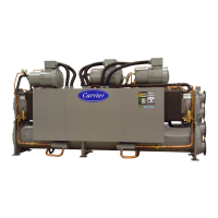
This publication contains Controls Start-Up, Service, Oper-
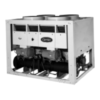
ation and Troubleshooting data for the 30GXN,R080-528 and
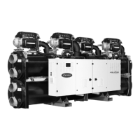
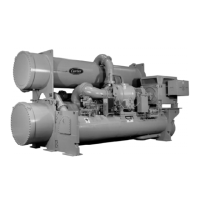
30HXA,C076-271 screw chillers.
Circuits are identified as circuits A and B, and compressors
areidentifiedasA1orA2incircuitA,andB1orB2in
circuit B. Refer to Appendix H for Duplex unit combinations.
The 30GXN,GXR,HX Series chillers feature microproces-
sor-based electronic controls and electronic expansion valves
(EXV) in each refrigeration circuit.
IMPORTANT: These units use refrigerant R-134a.
Compressor oil used with R-134a is Castrol Icematic
SW-220, Carrier Specification #PP47-32.
 Loading...


