49
LEGEND AND NOTES FOR TABLE
LEGEND
*Compressors are equipped with 2 motor winding temperature
thermistors. Verify first that the problem is not a wiring error
before using backup thermistor.
†Manual reset after 1 hour from occurrence.
**Reset automatic first time, manual if repeated on the same date.
††Note that the high-pressure switch should trip before this alert is
generated. Check HPS operation if this alert is generated.
***Maximum 5 power losses at CCP in one hour.
NOTES:
1. Low Oil Pressure Alert Criteria and Set Points
Where: P
d
= Discharge Pressure, P
s
= Suction Pressure.
P
o
= Oil Pressure and P
e
= Economizer Pressure
Two oil set points are used by the control for the Low Oil Pressure
alert trip.
Oil Set Point 1 is defined as:
a. If P
s
< 35, then Oil Set Point 1 = 10 psig.
b. If P
s
> 35 and < 51, then Oil Set Point 1 = 12.5 psig.
c. If P
s
≥ 51, then Oil Set Point 1 = 15 psig.
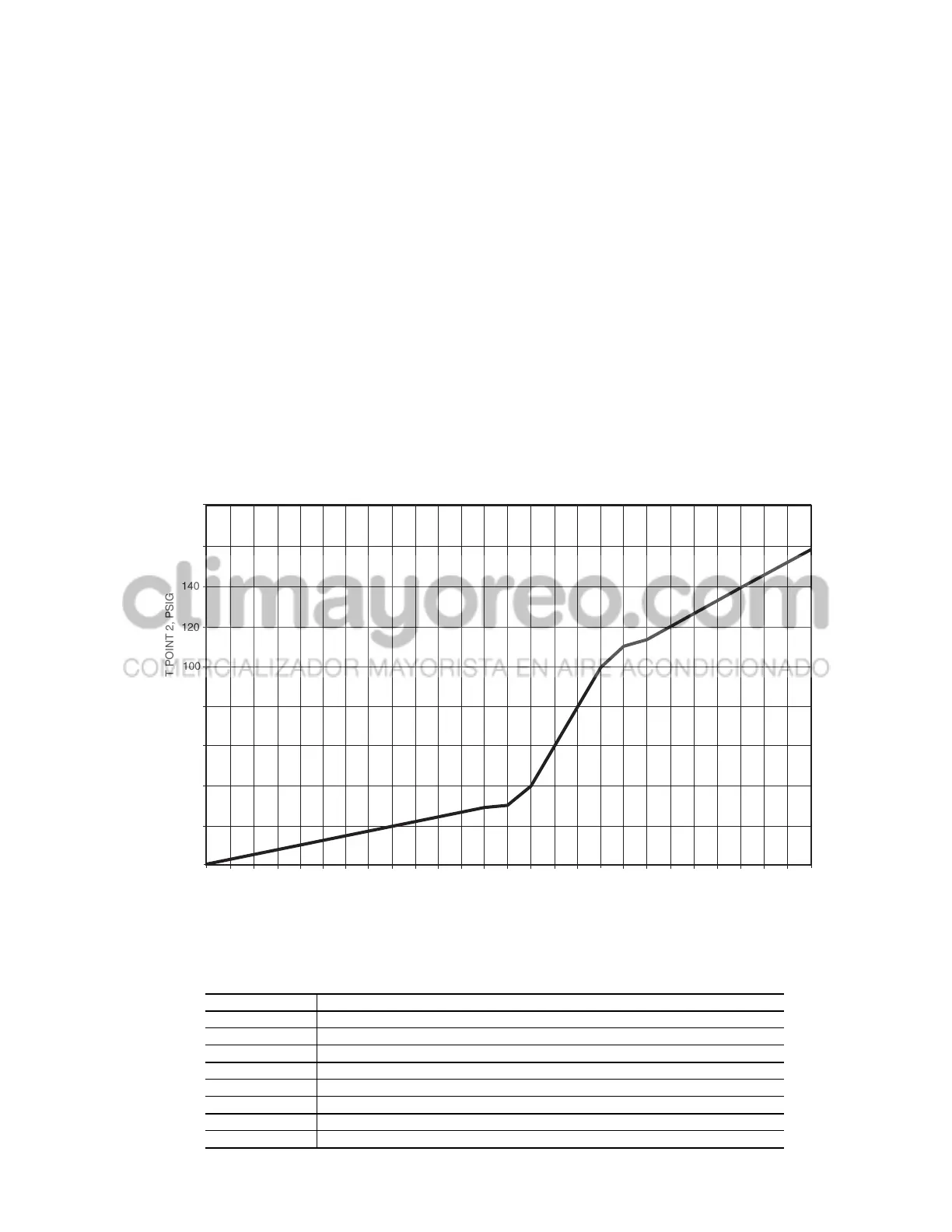
Oil Set Point 2 (see Fig. 20) is defined as:
a. If (P
d
–P
s
) < 125, then Oil Set Point 2 = 0.235 x (P
d
–P
s
)+
0.588
b. If (P
d
–P
s
) > 125 and < 165, then Oil Set Point 2 = 2.0 x
(P
d
–P
s
) – 220.0
c. If (P
d
–P
s
) ≥ 165 then Oil Set Point 2 = 0.6364 x (P
d
–P
s
)+
5.0
2. (P
o
–P
e
) is the Oil pressure differential displayed as items DO.A1
and DO.A2 (Pressures mode under sub-mode PRC.A) for
Circuit A and DO.B1 and DO.B2 (Pressures mode under sub-
mode PRC.B) for Circuit B.
3. Alert criteria is based on operating time.
a. On time less than 5 seconds oil pressure is ignored.
b. On time between 5 and 120 seconds, the alert will be gener-
ated if the following condition is true for 3 consecutive read-
ings:
(P
o
–P
e
)<[15 psig/120 sec.] x [Compressor Run Time in sec.]
c. On time greater than 120 seconds the alarm will be generated
if one of the following conditions is true:
(P
o
–P
e
) < Oil Set Point 1 for 15 seconds.
(P
o
–P
s
) < Oil Set Point 2 for 15 seconds.
Table 33 — Illegal Configurations (Alarm A151)
A/D — Analog to Digital Converter
CCN — Carrier Comfort Network
CCP —
Comfort
Link™ Compressor Protection
EMI — Electromagnetic Interference
EMM — Energy Management Module
EWT — Entering Water Temperature
EXV — Electronic Expansion Valve
HPS — High-Pressure Switch
LCW — Leaving Chilled Water
LWT — Leaving Water Temperature
MBB — Main Base Board
MCT_SP — Maximum Condensing Temperature Set Point
MTA — Compressor Must Trip Amps
SCB — Screw Compressor Board
SCT — Saturated Condensing Temperature
SST — Saturated Suction Temperature
TXV — Thermostatic Expansion Valve
WSM — Water-System Manager
CODE NUMBER ILLEGAL CONFIGURATION DESCRIPTION
1 Unit type outside range of 1-5
2 Number of compressors in Circuit A outside range of 1-2
3 Number of compressors in Circuit B outside range of 1-2
4 Invalid FAN.S or HPCT Selection
5 Air-cooled chiller with Low Temperature Brine fluid (FLUD = Low Brine)
6 Water-cooled chiller configured for air-cooled head pressure control type (HPCT)
7 Air-cooled chiller with condenser pump control enabled
8 Air-cooled chiller with condenser fluid sensors enabled
0
110
120 125
0
10 20 30
40
50
60
70
80
90 100
(DISCHARGE-SUCTION) PRESSURE, PSI
130
140 150 160 165
170
180
190 200 210
220
230
240
180
160
140
120
100
80
60
40
20
OIL PRESSURE SET POINT 2, PSIG
Fig. 20 — Oil Pressure Set Point 2 Calculation
 Loading...


