6
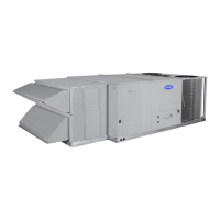
Fig. 9 — Connect EconomizerONE Harness to Unit
PL6 Economizer Harness
NOTE: Steps 11-15 apply to horizontal units only.
11. Attach filter panel above O/A panel. Slide under RTU (Pack-
aged Rooftop Unit) top flange then drop down until bottom
mount holes align with top holes on O/A panel. Fasten with
provided sheet metal screws. (See Fig. 10.)
12. Install the O/A hood to the O/A panel over the Economizer
assembly. Use screws provided. (See Fig. 10.)
13. Attach the R/A blank off panel, included with horizontal
economizers for large units only (see Table 2). See Fig. 11.
Grommet must be installed before duct work is installed.
14. Attach the O/A hood assembly to the O/A panel with
included screws. (See Fig. 10.)
15. Install provided barometric relief hood on field installed R/A
duct ensuring it is water tight. (See Fig. 12.)
16. Remove the indoor blower access panel and the panel(s) cov-
ering the unit control box. (See Fig. 13.) In the hardware kit
provided with the EconomizerONE is the POL 224 control-
ler. Mount the controller assembly on the left side of the unit
control box. Screw controller to the control box through pre-
punched holes in control box. (See Fig.14.)
17. Unplug the 12-pin female ECON plug currently connected to
the Unit Control Board (UCB). (See Fig. 15.)
18. Connect the 12-pin female ECON plug removed from the
UCB to the 12-pin male plug from the controller harness.
Refer to Fig. 16 and wiring diagram on page 9.
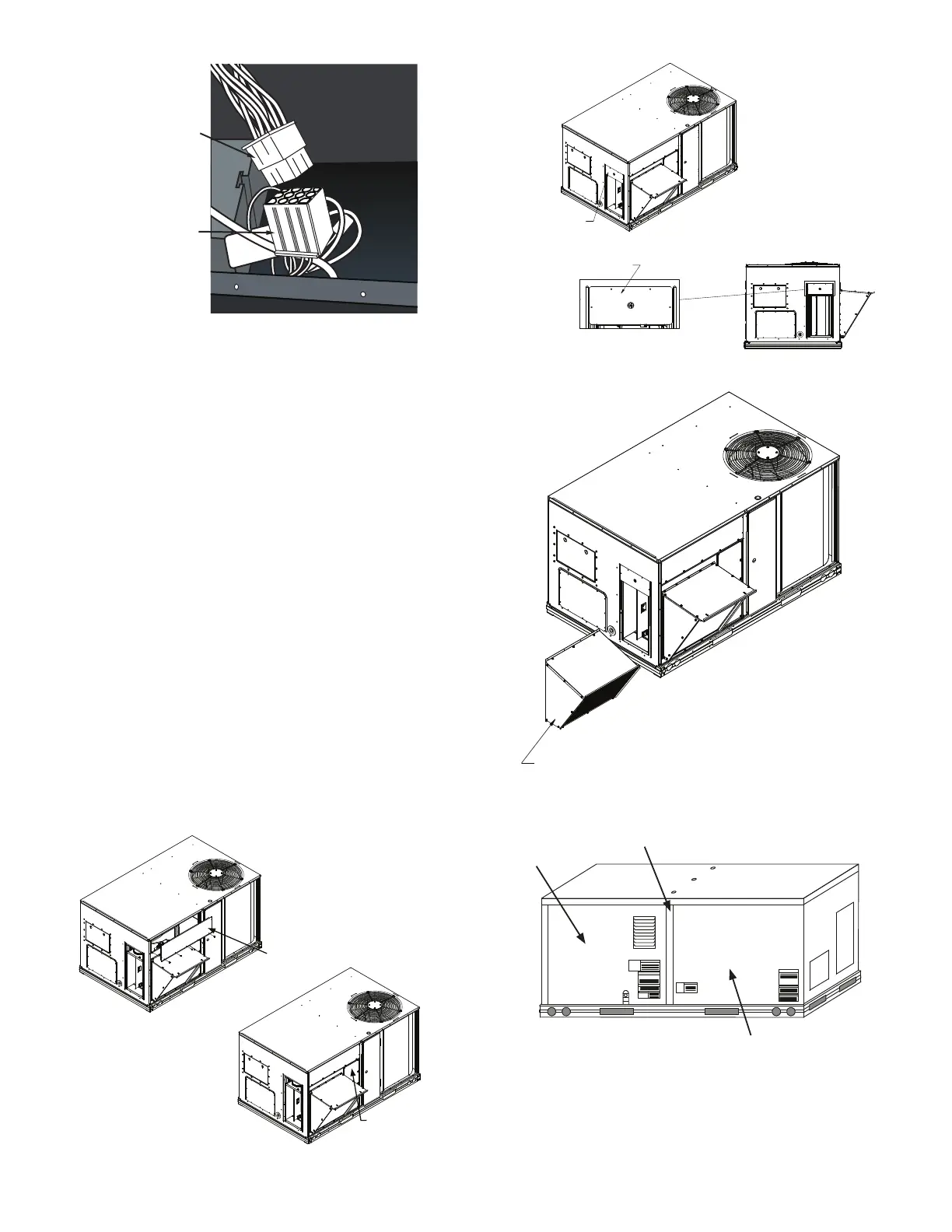
Fig. 10 — Attach Filler Panel and Hood
Fig. 11 — Attach R/A Blank Off Panel
Fig. 12 — Attach Relief Damper Hood Assembly to
Return Duct
Fig. 13 — Typical Indoor Fan Motor Access Panel
Locations
Rooftop Unit’s
12-Pin Male Plug
EconomizerONE
12-Pin Female Plug
Filter Panel
Filter Access
R/A Blank Off Panel
Attach R/A blank off
using 4 screws provided.
Ductwork not shown.
Unit Control
Box Panel(s)
Center Post
Indoor Blower
Access Panel
 Loading...