18
COOLING DELAY VIA INCREASING FAN SPEED
If there is cooling demand while outside air is suitable for econo-
mizing, then the economizer controller tries to increase fan
speed to maximize the use of outside air first. If the cooling de-
mand is not reached within a set time, then mechanical cooling
will be enabled.
Typical field application:
1. Prerequisites:
• Outside air is suitable for economizing and free cooling is
ON.
• Fan connected to the controller supports multiple speeds.
Cooling delay function does not work if only a one-speed
fan is connected to the controller.
2. If it is a 2-speed fan and there are two cooling demand inputs/
outputs, then Y1-Input is called and the controller sets fan
speed to Speed Low. Damper is fully open (100%).
a. If Y2-Input is also called, then the controller increases
fan speed to Speed High and starts fan delay (2FAN
DLY) time. After the delay time runs out, the controller
starts Y1-Output.
b. If the cooling demand is not reached within 3STG3 DLY
time and OAT is higher than MAT setpoint
(3MAT SET), then the controller starts Y2-Output.
DEMAND CONTROLLED VENTILATION (DVC)
If a field-installed CO
2
sensor is connected to the
EconomizerONE controller, then a demand controlled ventilation
strategy will operate automatically. As the CO
2
level in the space
increases above the setpoint (on the EconomizerONE controller),
the minimum position of the dampers will be increased propor
-
tionally, until the Maximum Ventilation setting is reached. As the
space CO
2
level decreases because of the increase in fresh air, the
outdoor damper will follow the higher demand condition from the
DCV mode or from the free cooling mode.
The controller modulates the outside air damper based on the CO
2
level through the ppm value selected between the range of 500 and
2000 ppm. The measured CO
2
concentration value is compared
with the set DCV setpoint. If the measured CO
2
concentration val-
ue is below the DCV setpoint, then keep the damper to the mini-
mum position. Otherwise, enable DCV. Once DCV is enabled, the
DCV PID starts to run to control the indoor CO
2
concentration
value towards the DCV setpoint. The damper opens to the maxi
-
mum position.
NOTE: DCV is disabled if the controller receives no occupancy
signal.
DCV operation is available in Occupied and Unoccupied periods
with EconomizerONE system. However, a control modification
will be required on the unit system to implement the Unoccupied
period function. Refer to Appendix B, Tables A-B
“Fixed Dry-
Bulb without DCV (CO2 Sensor) — 2-Speed Fan” on page 31
and “Fixed Dry-Bulb with DCV (CO2 Sensor) — 2-Speed Fan In
Conventional Mode” on page 32 for controls and command
operation.
HIGH HUMIDITY LIMITATION
The economizer controller applies high limit of humidity to
enthalpy-based economizing. When the OA dew point is below
the dew point setpoint, enthalpy-based economizing is avail
-
able. Otherwise, enthalpy-based economizing is unavailable.
ANTI-FREEZE PROTECTION
The economizer controller initiates the anti-freeze protection if
MAT or OAT temperature falls below the anti-freeze setpoint.
MAT-BASED ANTI-FREEZE PROTECTION
1. If MAT temperature falls below the anti-freeze setpoint
(3FRZ PROT), then:
• The controller closes both damper and compressor if unit
type is conventional unit and cooling/heating conventional
operation mode is enabled.
• The controller closes the damper if unit type is heat pump
and heat pump operation mode is enabled.
2. If the MAT sensor fails, then MAT is substituted by OAT to
continue the anti-freeze assessment. If OAT also fails, then
the controller closes the damper immediately.
OAT-BASED ANTI-FREEZE PROTECTION
If OAT temperature falls below the OAT lockout setpoint
(3OAT LOCK), then:
1. The controller stops the compressor from running if unit type
is conventional unit and cooling/heating conventional opera-
tion mode is enabled
2. The controller compressor is by-passed if unit type is heat
pump and heat pump operation mode is enabled.
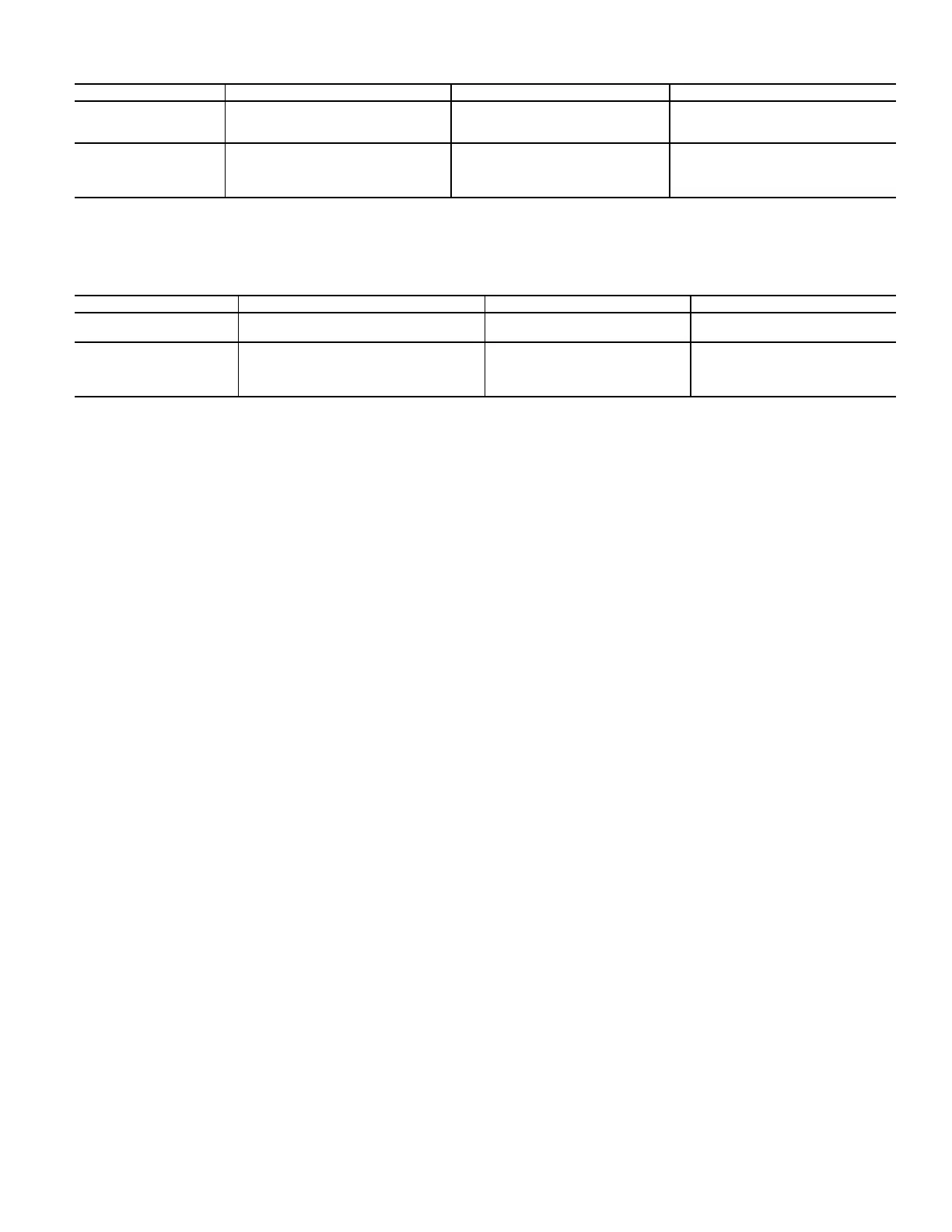
Table 16 — Different Damper Position Setting with Different Configured Outputs (DCV is Enabled)
FAN TYPE 1-STAGE COOLING
a
2-STAGE COOLING
a
3-STAGE COOLING
a
1-SPEED FAN
b
• 2VENTMIN H to 2VENTMAX H
(regardless of cooling demand,
OCC=Yes)
• 2VENTMIN H to 2VENTMAX H
(regardless of cooling demand,
OCC=Yes)
• 2VENTMIN H to 2VENTMAX H
(regardless of cooling demand
OCC=Yes)
2-SPEED FAN
• 2VENTMIN H to 2VENTMAX H
(regardless of cooling demand,
OCC=Yes)
• 2VENTMIN L to 2VENTMAXL
(0 or 1 cooling demand)
• 2VENTMIN H to 2VENTMAX H
(2 cooling demands)
• 2VENTMIN L to 2VENTMAX L
(0 or 1 cooling demand)
• 2VENTMIN H to 2VENTMAX H
(2 or 3 cooling demands)
a. Configured by Y1O, Y2O, or Y3O.
b. Configured by 6FAN.
Table 17 — Different Damper Position Setting with Different Configured Outputs
(DCV is Disabled, CO
2
sensor is connected)
FAN TYPE 1-STAGE COOLING
a
2-STAGE COOLING
a
3-STAGE COOLING
a
1-SPEED FAN
b
• 2VENTMIN H (regardless of cooling
demand, OCC=Yes)
• 2VENTMIN H (regardless of
cooling demand, OCC=Yes)
• 2VENTMIN H (regardless of
cooling demand, OCC=Yes)
2-SPEED FAN
b
• 2VENTMIN H (regardless of cooling
demand, OCC=Yes)
• 2VENTMIN L
(0 or 1 cooling demand)
• 2VENTMIN H
(2 cooling demands)
• 2VENTMIN L (0 or 1 cooling
demand)
• 2VENTMIN H (2 or 3 cooling
demands)
a. Configured by Y1O, Y2O, or Y3O.
b. Configured by 6FAN.
 Loading...