ELECTRICAL INSTALLATION
A)I wiring must comply withapplicable local and national codes.
I Be sure all incoming power is OFF before beginning any procedures.
I The following instructionsare for use by qualified personnel only.
I _
L J
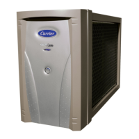
The Electronic Air Cleaner (without the AFS installed at the factory) is designed to take advantage of the integrated
accessory control panel available on most furnaces. The 12OV Electronic Air Cleaner tap on the furnace will provide
power to the air cleaner only when the circulating air blower isin operation.
Read the instructions in the furnace installation manual carefully before attempting instal_efion or operation. Failure to
follow these instructions may result in improper installation and therefore void warranty.
An optionef(on 120v model) electronic air l_ow sensor kit isavailable ifthe air cleaner is not equipped with an AFS. This
air _ow sensor will sense the air movement w_thin the duct and turn the Electronic/_r Cleaner on and off accordingly.
Figure 8
• I [IW:_.lllllt|] _
WIRING PROCEDURE
This air cleaner is powered by providing power to pigtail
leads at field wiring compartment (see knoCk-Out holes)
loCated at the rear of the power pack assembly (See Fig.
0).
1. Turn air cleaner OFF using ON/OFF switch located on
front panel.
2. Remove power pack cover plate by removing front
door and two screws holding assembly to the top of
theair cleaner.
3. Make wiring connections inside junction box area
(See Fig. 8). Remove knOCk-Out and use conduit or
other approved methods to supply input power.
Connect g round wire to clip.
4. Replace the power supply cover plate and secure with
screws removed from step 2.
5. Replacethe unit door to the front of the air cleaner.
6, Air cleaner will now operate when door is Ln place,
ON/OFF rocker switch is inthe ON position and input
voltage is present in the junction box. The following
should be oompIcted to supply input power to the _r
cleaner.
FURNACE APPLICATION
It is recommended to use EAC t and EAC 2 terminals
when provided by the furnace circuit hoard. These
outputs will provide 120 vac whenever the blower motor
isenergized.
Furnace circuit boards without EAC 1 and EAC 2
terminals MUST use alternate methods to supply to
supply power to the air cleaner. Options include Sail
Switch, Isolation relay or Optional AFS (Air F!ow Sensor)
Air cleaner should only operate when blower motor is
running.
This unit cannot be powered directly from blower motor
/
leads. Voltages can exceed t 90vac for 120-v. motors or
possibly double with 240-v fan coil motors, j
FAN COIL APPLICATION of 0014 or 0020 Models (120-v.)
if EAC I and F_AC2 terminals are provided by fan coil
circuit board, refer to fan coil data to determine voltage
output. Most fan coils do not provide 120-v. at these
termina!s. Alternate methods may be needed to eonved
fan coil supply voltage to 120-v. for the cleaner. A 240-v. to
120-v step down transformer (60 v) will be needed in most
applications. Sail Switch, Isolation relay or Optional AFS
(Air Flow Sensor) may also be needed,
FAN COIL APPLICATION of 2020 Model (240-v.)
The Model 2020 is a 240-v, power supply model designed
to match you fan coil, To installthis model with a g40-v, far_
coil:
_|_:tl| I[IU
I This unit cannot he powered directly from blower motor
leads. Back EMF (electro magnetic field) voltages can
l reach40Ovao or240-v.fanco mo ors. J
1. "rum air cleaner OFF using ON/OFF rocker switch
loCated on front panel
2, Remove power pack cover plate by removing front
door and two screws holding assembly to the top of the
aircteanec
3. Make wiring connections inside )unction box area (See
Fig 8). Remove knock-out and use conduit or other
approved methods to supply input powe_ Connect
ground wireto clip,
4. Rep(ace the power supply cover plate and secure with
screws removed from step 2.
5.Replace the unit door to the front of _heair cleaner.
6. Air cleaner will now operate when door in place,
ON/OFF rocker switch is in the ON position and input
voltage is present in the junction box.
22

 Loading...
