EasyManua.ls Logo

Carrier HRVXXSHA1160 - User Manual

Carrier HRVXXSHA1160
18 pages
Print Icon
To Next Page IconTo Next Page
Loading...
User and Installer Manual
A200557
INSTALLER: READ THESE INSTRUCTIONS BEFORE INSTALLING UNIT.
SAVE THEM FOR THE USER.
RESIDENTIAL USE ONLY
REGISTER YOUR PRODUCT ONLINE AT: www.cac-bdp-all.com For additional information, https://www.hvacpartners.com/
A200637
65% SRE ERV Models are not ENERGY STAR certified
Consumer Information
A. To ensure quiet operation of the ENERGY STAR certified H/ERV, each product model must be installed using sound attenuation techniques
appropriate for the installation.
B. The way your heat/energy-recovery ventilator is installed can make a significant difference to the electrical energy you use. To minimize the
electricity use of the heat/energy-recovery ventilator, a stand-alone fully ducted installation is recommended. If you choose a simplified installation
that operates your furnace air handler for room-to-room ventilation, an electrically efficient furnace that has an electronically commutated (EC)
variable speed blower motor will minimize your electrical energy consumption and operating cost.
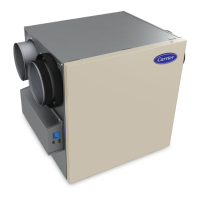
ERV & HRV
Fresh Air Systems
ERVXXSHA1130, ERVXXSVA1130, HRVXXSHA1130, HRVXXSVA1130
ERVXXSHA1150, ERVXXSVA1150, ERVXXSHB1145, ERVXXSVB1145
HRVXXSHA1160, HRVXXSVA1160, HRVXXSHB1160, HRVXXSVB1160

Questions and Answers

Summary

Safety, Limitations, and Cautions

Critical Safety Warnings

Essential warnings regarding fire, electric shock, and personal injury hazards.

Unit Damage Prevention Cautions

Cautions to prevent unit damage and ensure longevity through correct usage.

Air Distribution and Installation Overview

Unit Installation and Mounting

Guidance on choosing an appropriate location and mounting methods (suspended/wall).

Ductwork and System Configurations

Installing Ductwork and Registers

Procedures for installing ductwork and registers for Fully Ducted (T-1), Exhaust (T-2), and Alternate (T-3) systems.

Auto-Balancing and Unit Usage

Unit Auto-Balancing Procedure

Detailed steps for preparing, performing, and resetting the auto-balancing process.

Installer Troubleshooting Guide

Error Code Diagnosis and Resolution

Troubleshooting common error codes (E01-E60, W22-W61) for system components.

Maintenance Procedures

Quarterly Maintenance Tasks

Step-by-step guide for performing quarterly cleaning and checks.

Overview

This document is a User and Installer Manual for ERV & HRV Fresh Air Systems, specifically covering models ERVXXSHA1130, ERVXXSVA1130, HRVXXSHA1130, HRVXXSVA1130, ERVXXSHA1150, ERVXXSVA1150, ERVXXSHB1145, ERVXXSVB1145, HRVXXSHA1160, HRVXXSVA1160, HRVXXSHB1160, and HRVXXSVB1160. The manual provides comprehensive information for both installation and ongoing use, emphasizing safety, proper setup, and maintenance to ensure optimal performance and longevity of the unit.

Function Description

The ERV (Energy Recovery Ventilator) and HRV (Heat Recovery Ventilator) units are balanced ventilation systems designed to provide fresh air to a home while exhausting stale, humid air. They incorporate an energy/heat recovery module that reclaims a significant portion of indoor or outdoor air energy, depending on the season. This process enhances comfort and energy efficiency during both heating and cooling periods. The new ventilation technology allows the unit to autonomously adapt to environmental variations, maintaining appropriate ventilation and air quality levels. In colder climates, the unit performs discreet defrost cycles at intervals to sustain performance and comfort.

Important Technical Specifications

The manual highlights that dimensions, performance charts, defrost cycle tables, and specifications are detailed on the unit's specification sheets, accessible via the manufacturer's website. Key installation requirements include:

  • Residential Use Only: The units are intended solely for domestic installation.
  • Electrical Wiring: Must be performed by a qualified person in accordance with all applicable codes and standards, including fire-rated construction codes.
  • Grounding: The unit must be grounded via a 3-prong grounding plug connected to a mating 3-prong grounding receptacle. Extension cords are not to be used.
  • Speed Control: Only solid-state speed control devices specified in the manual (CONNECTIONS section) should be used.
  • Ductwork: Must be installed in compliance with all applicable local and national codes. Air ducts should not run directly above or within 2 feet (0.61 m) of a furnace or other heat-producing appliances. If connected to a furnace return plenum, it must be at least 10 feet (3.1 m) away from the plenum's connection to the furnace.
  • Outdoor Air Intake/Exhaust: Must be ducted outside, not into attics, crawl spaces, or garages. Exhaust air from dryers or range hoods should not be recovered.
  • Drainage (HRV Only): HRV units require a drain hose installation due to potential water generation, especially in cooler weather. A water trap loop in the tube is necessary to prevent odors.
  • Tandem® Transition Kit (Optional): For units set at 110 CFM or less, this kit can replace two exterior hoods, but it will generate an additional 0.2 in w.g. static pressure. Minimum joist opening for installation is 9¾", maximum height is 8½".
  • Duct Sizing: For 130 CFM units, transitioning to 6-inch ducts requires 5-inch to 6-inch transitions on the ports, secured with duct tape. Rigid ducting should include a 12-inch section of flexible duct between the transition and rigid ducting to prevent vibration transmission.
  • Electrical Connections: Low voltage class 2 circuits are used for furnace/AHU interlock. Never connect a 120V AC circuit to these terminals. Wall control wiring should avoid proximity to control contactors, light dimming circuits, electrical motors, or power distribution panels to reduce interference.

Usage Features

The units offer various operational modes and controls:

  • Integrated Control: Located on the front of the electrical compartment, it allows users to select modes (Standby, Min, Max) and adjust CFM settings.
  • Optional Wall Controls: Units can be controlled via an optional main wall control (Speed Selector, Automatic, Dehumidistat, Premium Optional Main Wall Control) or an optional auxiliary wall control (Bathroom Override). These override the integrated control.
  • Furnace/AHU Thermostat Integration: If the thermostat has an optional ventilation output, it can operate the unit in MIN, intermittent, AUTO (based on outdoor temperature), or MAX speed in DRY option when the VENT contact is activated. This option overrides the main wall control.
  • Synchronization with AHU: The unit can synchronize its operation with the furnace/AHU to prevent unnecessary AHU operating time and improve air distribution. This is crucial for T-2, T-3, T-4, and T-5 duct configurations.
  • Auto-Balancing Procedure: This ensures accurate airflow measurements. It involves sealing ductwork, closing windows and doors, turning off other exhaust devices, and adjusting CFM settings on the LCD screen. Installation configuration (T-1, T-2, T-3, T-4, T-5) must be selected during this process. Options for defrost (DIS, PLU), override (BAL, PER, DIS), and intermittent (STB) modes are configurable.
  • Protection Mode (W61): If electronics overheat (e.g., in warm environments above 60°C/140°F), the unit reduces power to motors to decrease temperature. Airflows may be reduced during this period.

Maintenance Features

Regular maintenance is crucial for the unit's performance and longevity:

  • Quarterly Maintenance:
    • Disconnect power.
    • Open and clean the unit door with a damp cloth.
    • Remove and clean filters: Vacuum dust, wash with warm water and mild soap (bleach can be added for disinfection), rinse thoroughly, and air dry. MERV13 filters are not washable.
    • Clean the condensing tray with a damp cloth.
    • Check the exterior air intake hood for obstructions (leaves, twigs, ice, snow) and clean if necessary.
    • Reassemble components, ensuring filters are properly seated.
    • Rotate blower wheels by hand to check for smooth operation.
    • Close the door and reconnect power.
    • Reset filters via the optional main wall control (INT/AUTO button for 5 seconds) or touch screen for advanced controls.
  • Annual Maintenance (at Fall):
    • Repeat quarterly steps 1-6.
    • HRV Models: Remove the core, soak it in a mixture of cold/lukewarm water and mild soap, rinse thoroughly, shake to remove excess water, and let dry. Clean blower assemblies with a vacuum cleaner and soft brush attachment.
    • ERV Models: Remove dust from the core using a vacuum cleaner and a soft brush attachment. Do not soak the energy recovery core in water.
    • Reassemble components and reconnect power.
  • Troubleshooting: The manual provides detailed troubleshooting tables for both installers and users, addressing common errors (e.g., damper issues, motor problems, airflow issues, thermistor faults, wall control communication) and offering step-by-step solutions. For unresolved issues, users are advised to contact their local dealer.
  • Replacement Parts: Emphasizes the use of genuine manufacturer replacement parts to ensure safety, performance, and compliance with certification standards. A service parts list with part numbers is provided, along with a model-specific electronic assembly part number matrix.

Carrier HRVXXSHA1160 Specifications

General IconGeneral
BrandCarrier
ModelHRVXXSHA1160
CategoryAir Cleaner
LanguageEnglish

Related product manuals