ERV & HRV: User and Installer Manual
Manufacturer reserves the right to change, at any time, specifications and designs without notice and without obligations.
1
User and Installer Manual
A230249
INSTALLER: READ THESE INSTRUCTIONS BEFORE INSTALLING UNIT.
SAVE THEM FOR THE USER.
RESIDENTIAL USE ONLY
REGISTER YOUR PRODUCT ONLINE AT: www.cac-bdp-all.com For additional information, https://www.hvacpartners.com/
A200637B
Consumer Information
A. To ensure quiet operation of the H/ERV, each product model must be installed using sound attenuation techniques appropriate for the installation.
B. The way your heat/energy-recovery ventilator is installed can make a significant difference to the electrical energy you use. To minimize the
electricity use of the heat/energy-recovery ventilator, a stand-alone fully ducted installation is recommended. If you choose a simplified installation
that operates your furnace air handler for room-to-room ventilation, an electrically efficient furnace that has an electronically commutated (EC)
variable speed blower motor will minimize your electrical energy consumption and operating cost.
1112137 rev. B
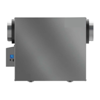
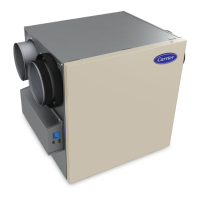
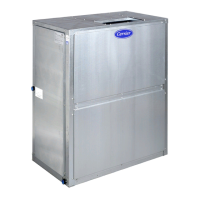
ERV & HRV
Fresh Air Systems
ERVXXLHB1210**, HRVXXLHB1230**
** These products earned the Energy Star®
by meeting strict energy efficiency guide-
lines set by Natural Resources Canada and
the US EPA. They meet Energy Star®
requirements only when used in Canada.